
Dielectric barrier discharge lamp with electrodes in hexagonal arrangement

a discharge lamp and hexagonal arrangement technology, applied in the direction of gas-filled discharge tubes, multiple discharge path lamps, solid cathodes, etc., can solve the problems of prone to deterioration, electrode configuration does not provide a sufficiently homogenous light, and the planar lamp configuration cannot be used in the majority of existing lamp sockets and lamp housings, etc., to achieve uniform and homogenous discharge, reduce the available discharge volume, and improve the effect of efficiency

Inactive Publication Date: 2008-11-04
GENERAL ELECTRIC CO
View PDF7 Cites 2 Cited by
  • Summary
  • Abstract
  • Description
  • Claims
  • Application Information

AI Technical Summary

Benefits of technology

[0003]A majority of presently known and commercially available low pressure discharge lamps are the so-called compact fluorescent lamps. These lamps have a gas fill, which also contains small amounts of mercury. Since mercury is a highly poisonous substance, novel types of lamps have been developed recently. One promising candidate to replace mercury-filled fluorescent lamps is the so-called dielectric barrier discharge lamp (shortly DBD lamp). Besides eliminating the mercury, it also offers the advantages of long lifetime and negligible warm-up time.
[0008]Accordingly, there is a need for a DBD lamp configuration with an improved discharge vessel-electrode configuration, for which the ignition is easy to start and keep active, without the need for high operating voltages. There is also need for an improved discharge vessel-electrode configuration which ensures that the electric field and the discharge within the available discharge volume is homogenous and strong, and thereby substantially the full volume of a lamp may be used efficiently. It is sought to provide a DBD lamp, which, in addition to having an improved discharge vessel-electrode arrangement, is relatively simple to manufacture. Further, it is sought to provide a discharge vessel-electrode configuration, which readily supports different types of electrode set configurations, according to the characteristics of the used discharge gas, exciting voltage, frequency and exciting signal shape. The proposed electrode arrangement minimizes the self-shadowing effect of the electrodes in order to provide for a higher luminance and efficiency.SUMMARY OF THE INVENTION
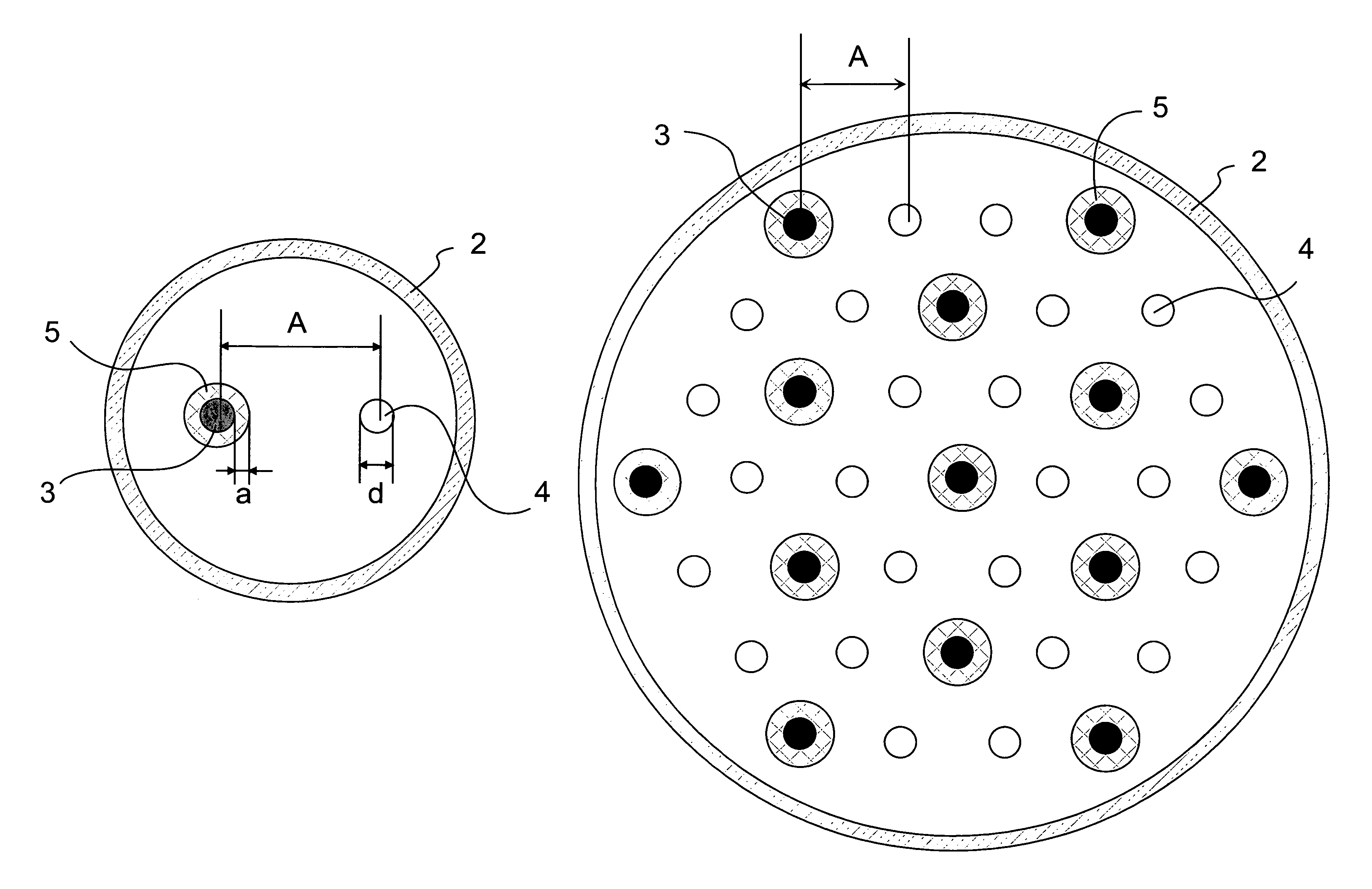
[0011]The disclosed DBD lamps have several advantages over the prior art. They ensure that the available discharge volume is fully used to receive the electrodes of both type (cathodes and anodes) and no other elements are located within the discharge vessel that would decrease the available discharge volume and cause certain shadowing effect. The arrangement of the electrodes of different type inside the discharge vessel and parallel to each other will enable the use of a power supply delivering exiting voltages of 1-5 kV with a frequency in the kHz range. The density of the lines of force of the electric field is substantially higher than in known conventional lamp configurations with external electrodes. The lamp according to the invention will operate with a good efficiency. In addition to this, the lamp can provide a uniform and homogenous volume discharge, and a large illuminating surface.

Problems solved by technology

This is advantageous because a thin film dielectric layer is complicated to manufacture and it is prone to deterioration.
On the other hand, a planar lamp configuration cannot be used in the majority of existing lamp sockets and lamp housings, which were designed for traditional incandescent bulbs.
It has been found that such an electrode configuration does not provide a sufficiently homogenous light, because the discharge within the relatively large discharge volume tend to be uneven.
Certain volume portions are practically completely devoid of an effective discharge, particularly those volume portions, which are further away from both electrodes.

Method used


Image

  • Dielectric barrier discharge lamp with electrodes in hexagonal arrangement
  • Dielectric barrier discharge lamp with electrodes in hexagonal arrangement
  • Dielectric barrier discharge lamp with electrodes in hexagonal arrangement

Examples


Embodiment Construction

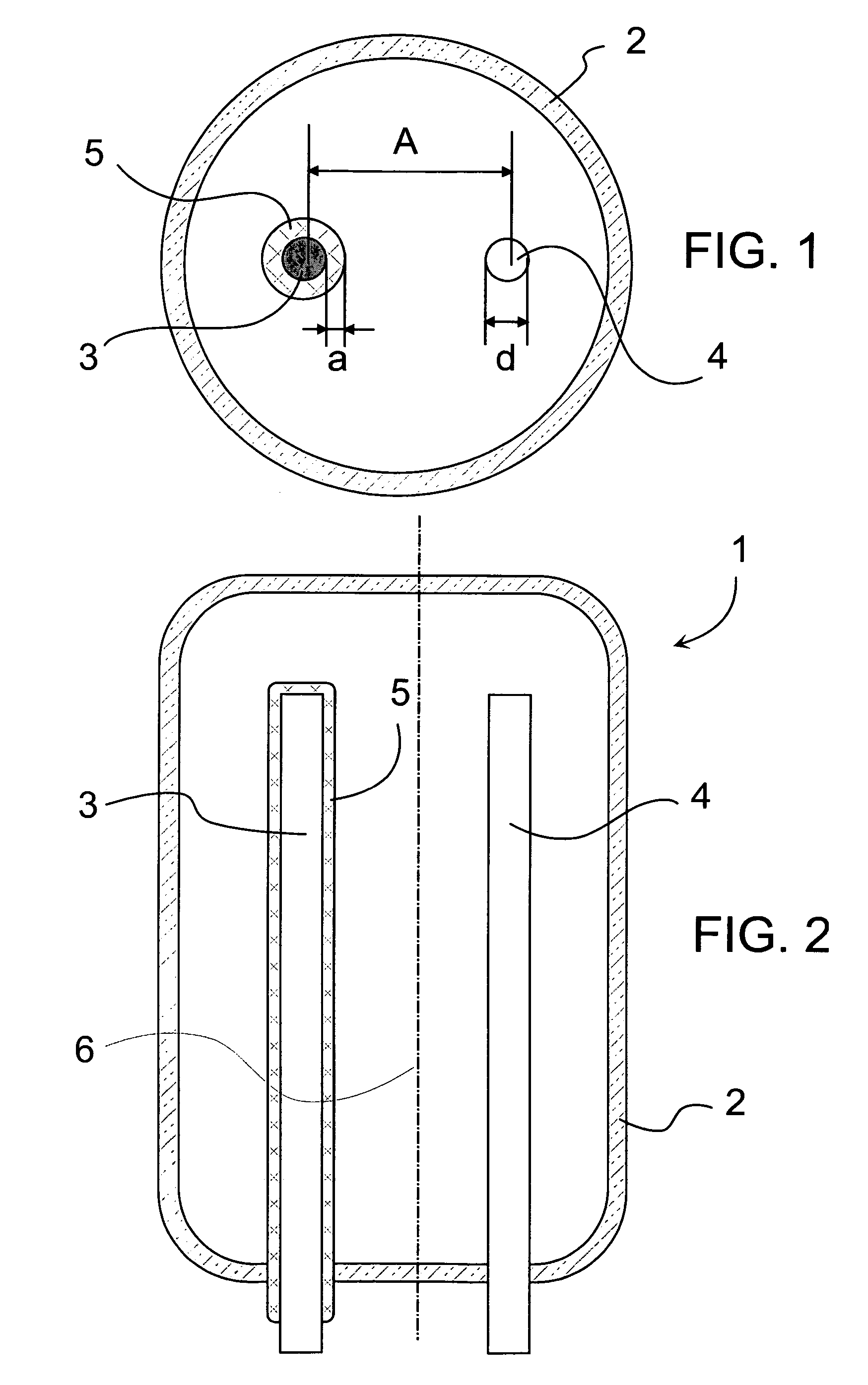
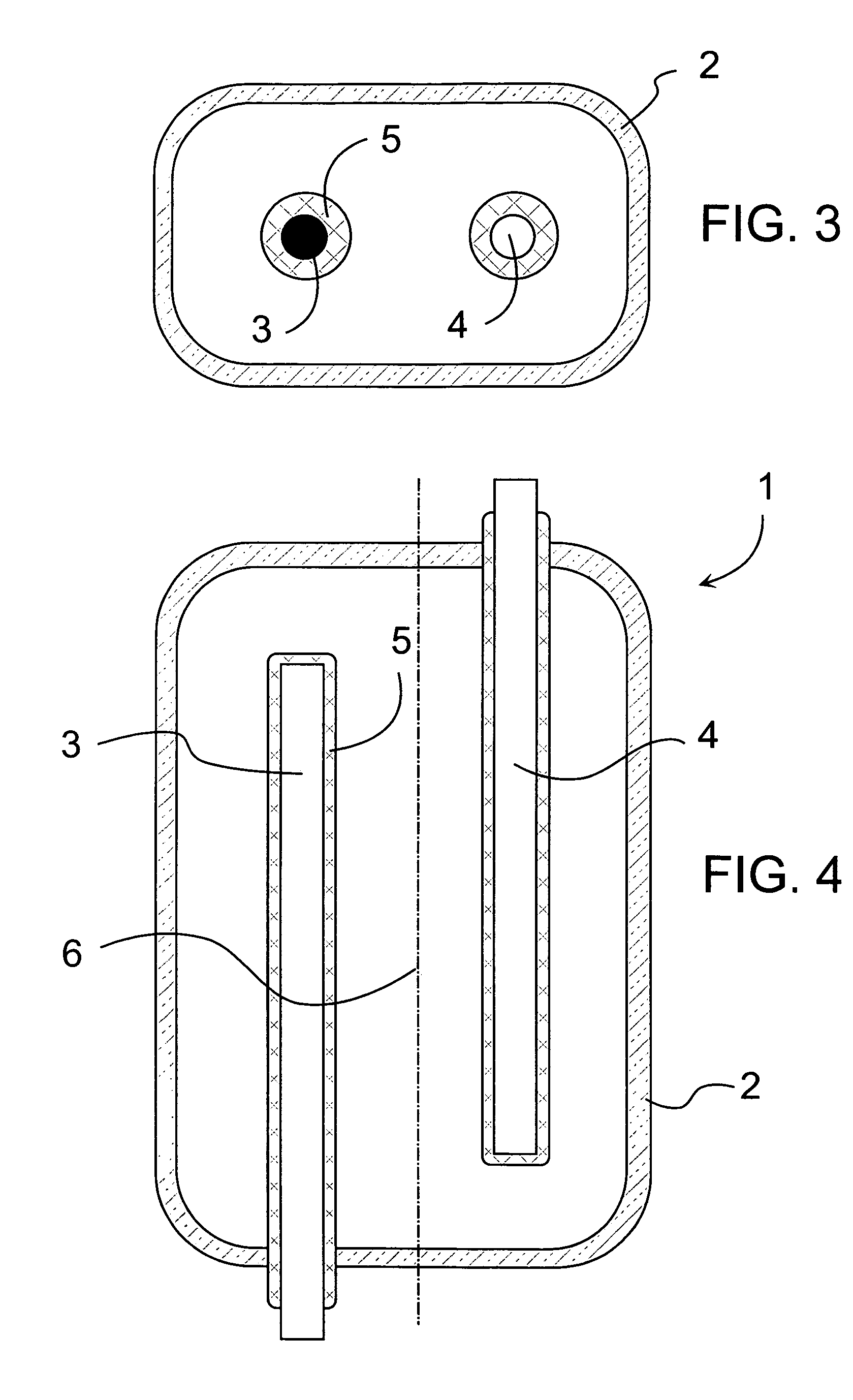
[0022]Referring now to FIGS. 1 and 2, there is shown a schematic picture of a low pressure discharge lamp 1. The lamp is a dielectric barrier discharge lamp (hereinafter also referred to as DBD lamp), with a single discharge vessel 2 serving also as an envelope of the DBD lamp. The discharge vessel 2 encloses a discharge volume, which is filled with discharge gas. The wall of the discharge vessel may be coated with a luminescent layer in order to convert short wave radiation of the excited gas into visible light. In the shown embodiment, the discharge vessel is substantially cylindrical and made of a transparent material, which may be a soft or hard glass or any suitable ceramic material which is transparent to the wavelength emitted by the lamp. For reason of higher security, a separate external envelope (not shown) may also be used, which may be made of the same material as the discharge vessel or a suitable plastic material which is transparent to the wavelengths emitted by the l...


PUM


Abstract

A dielectric barrier discharge lamp comprises a discharge vessel that has a principal axis, the discharge vessel encloses a discharge volume filled with a discharge gas. The discharge vessel further comprises end portions intersected by the principal axis. There are at least one electrode of a first type and at least one electrode of a second type in the lamp. The electrodes of one type are energized to act as a cathode and the electrodes of other type are energized to act as an anode. The electrodes are substantially straight, elongated and have a longitudinal axis substantially parallel to the principal axis of the discharge vessel. These electrodes are positioned within the discharge volume. The electrodes of at least one type are isolated from the discharge volume by a dielectric layer. A dielectric barrier discharge lamp is also disclosed, in which the electrodes are arranged within the discharge volume in groups, and each of the groups comprises one electrode of the first type and at least one electrode of the second type.

Description

BACKGROUND OF THE INVENTION[0001]This application is a continuation-in-part application of U.S. Ser. No. 10 / 855,347, filed on 6 Jul. 2004, which is hereby incorporated by reference in its entirety.[0002]This invention relates to a dielectric barrier discharge lamp.[0003]A majority of presently known and commercially available low pressure discharge lamps are the so-called compact fluorescent lamps. These lamps have a gas fill, which also contains small amounts of mercury. Since mercury is a highly poisonous substance, novel types of lamps have been developed recently. One promising candidate to replace mercury-filled fluorescent lamps is the so-called dielectric barrier discharge lamp (shortly DBD lamp). Besides eliminating the mercury, it also offers the advantages of long lifetime and negligible warm-up time.[0004]As explained in detail in U.S. Pat. No. 6,060,828 for example, the operating principle of DBD lamps is based on gas discharge in a noble gas (typically Xenon). The disch...

Claims


Application Information

Patent Timeline
Patent Type & Authority Patents(United States)
IPC IPC(8): H01J29/87
CPCH01J61/92H01J65/046
Inventor REICH, LAJOSAGOD, ATTILABELEZNAI, SZABOLCSJAKAB, LASZLORICHTER, PETER
Owner GENERAL ELECTRIC CO
Learn More