Piezoelectric sounding body and electronic device using the same

a technology of electronic equipment and piezoelectric sounding body, which is applied in the direction of piezoelectric/electrostrictive/magnetostrictive devices, deaf-aid sets, mechanical vibration separation, etc., can solve the problem of possibly insufficient reliability, and achieve the effect of improving the freedom of mounting, reducing the thickness of the piezoelectric sounding body, and improving the electrode structur

Inactive Publication Date: 2008-11-04
TAIYO YUDEN KK
View PDF11 Cites 8 Cited by
  • Summary
  • Abstract
  • Description
  • Claims
  • Application Information

AI Technical Summary

Benefits of technology

[0007]It is an object of the present invention to reduce the thickness of a piezoelectric sounding body by improving the electrode structure, thereby improving the freedom of mounting to an electronic device and reducing the thickness of the electronic device itself. Another object of the invention is to improve the reliability of electrode lead. A further object of the invention is to simplify the manufacturing process and diminishing materials by virtue of an improved lead structure.
[0008]In one aspect of the invention, there is provided a piezoelectric sounding body for a sound producer, comprising: a piezoelectric element comprising at least one piezoelectric layer and electrode layers respectively provided on main surfaces of the piezoelectric layer in a manner sandwiching the piezoelectric layer, wherein each main surface of the piezoelectric layer is divided into multiple sections, and each electrode layer is divided, separated, and disposed respectively on the multiple sections in positions which are substantially the same between the both main surfaces sandwiching the piezoelectric layer; a diaphragm having surfaces to at least one of which the piezoelectric element is bonded; and a plurality of connectors each connecting, thicknesswise of the piezoelectric layer, one section of the electrode layer on the main surface of the piezoelectric layer to one section of the other opposing electrode layer via the piezoelectric layer corresponding to another section of the electrode layer that is adjacent to the one section of the electrode layer on the same main surface, in a position where the one section of the other opposing electrode layer overlaps any section of the electrode layer on said main surface. This structure allows for leading electrodes all at the diaphragm, thus reducing the overall thickness and improving the reliability.
[0009]In one embodiment, at least one of the plurality of connecting means has a through-hole. In another embodiment, a plurality of lead electrodes are provided, on a main surface of the diaphragm, that are conductively connected respectively to the divided multiple sections of the electrode layer on each main surface of the piezoelectric layer. In still another embodiment, each electrode layer is divided into the multiple sections using a division line, as a boundary, not passing a center of the main surface of the piezoelectric layer, or each electrode layer on the same main surface of the piezoelectric layer is divided into the multiple sections arranged substantially concentric about a center of the piezoelectric layer. The structure in any of the foregoing provides the effect of manufacturing process simplification and material diminishing by a simplified lead structure.

Problems solved by technology

Thus, the reliability is possibly insufficient for the severity of piezo-driving over a long time.

Method used


Image

  • Piezoelectric sounding body and electronic device using the same
  • Piezoelectric sounding body and electronic device using the same
  • Piezoelectric sounding body and electronic device using the same

Examples


first embodiment

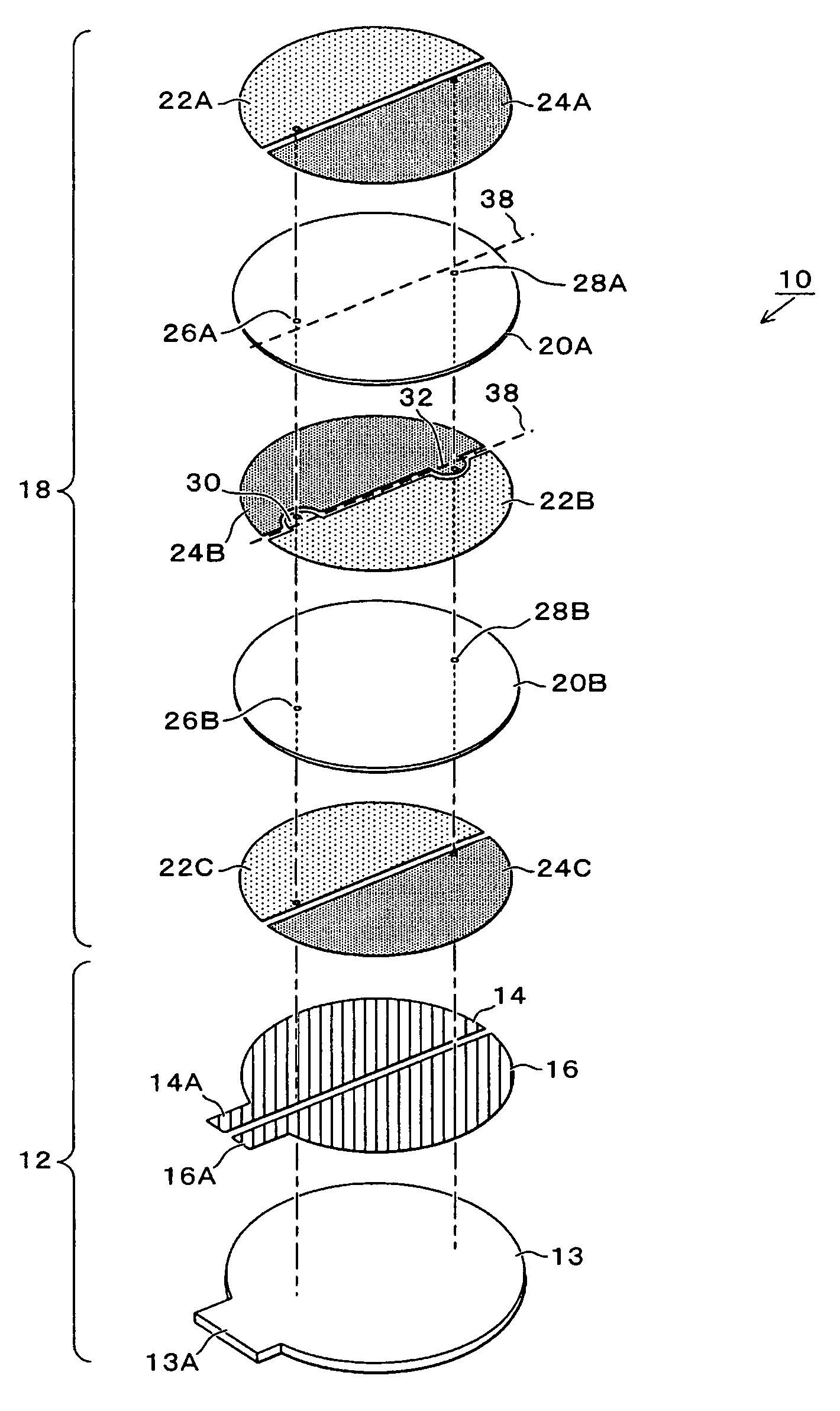
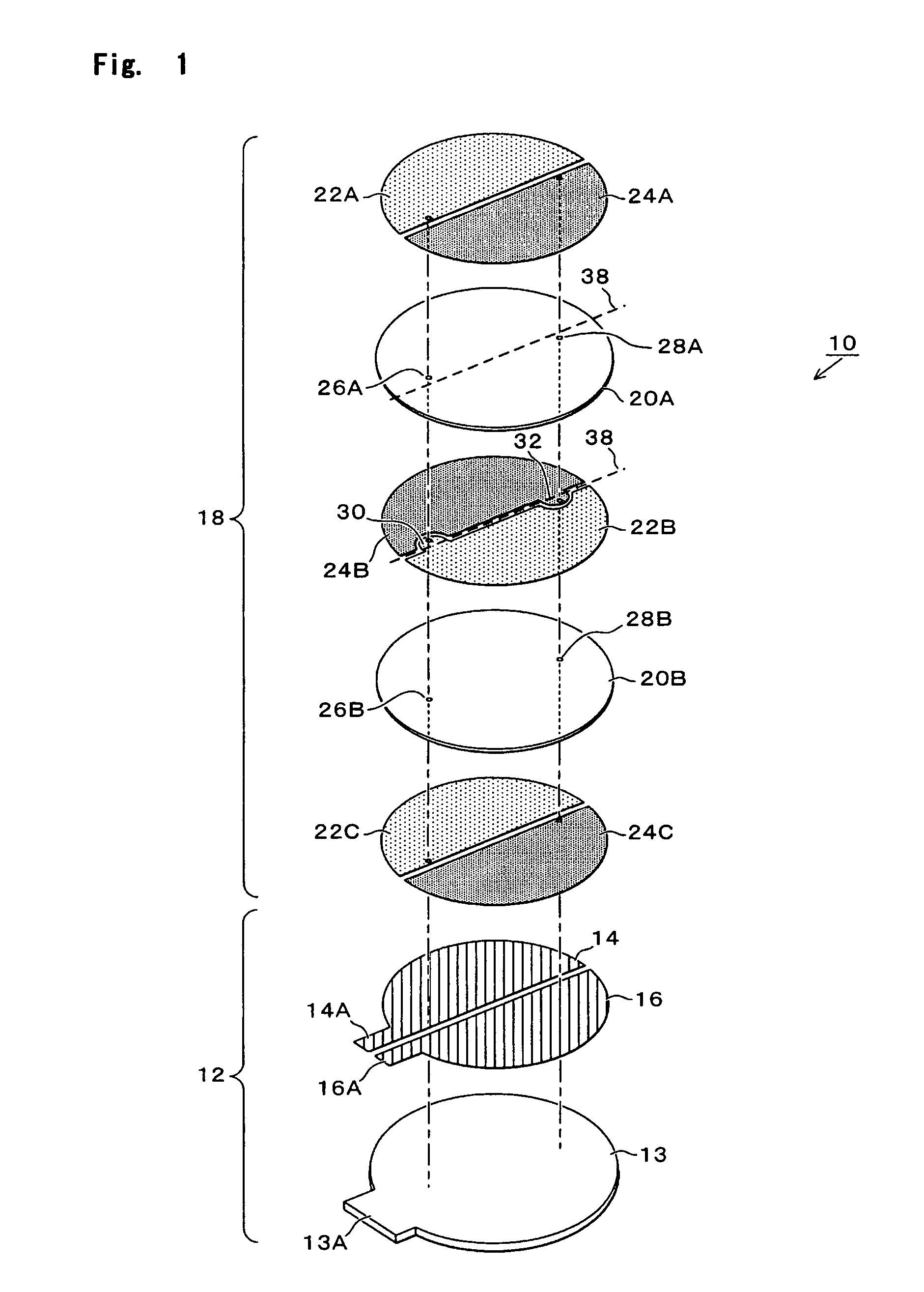
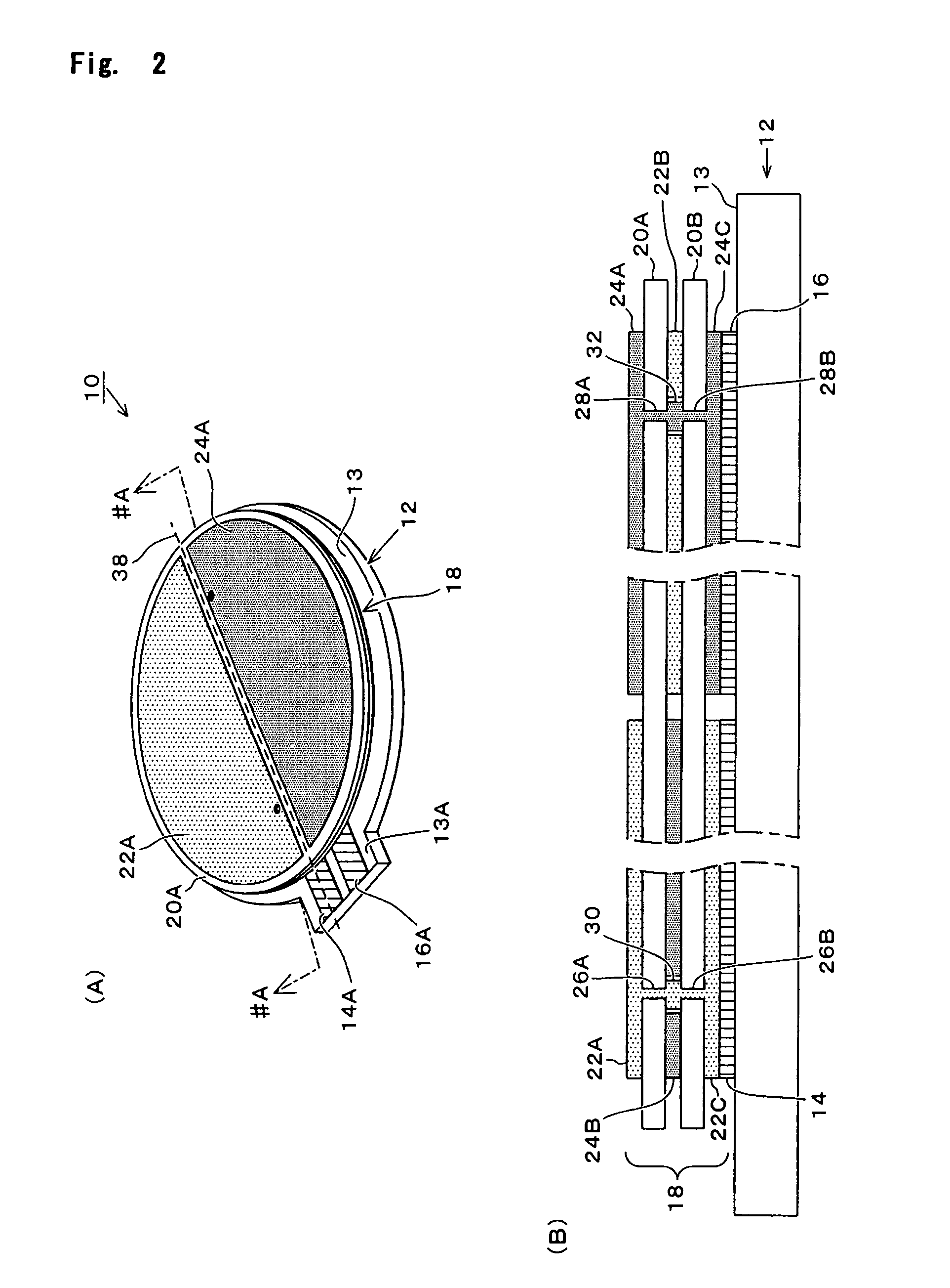
[0036]Referring to FIGS. 1 to 3, description is now made on a first embodiment of the invention. FIG. 1 is an exploded perspective view showing a structure in the present embodiment. FIG. 2A is an exterior perspective view showing the entire of the present embodiment while FIG. 2B is a sectional view of the FIG. 1 structure, taken along line #A-#A, as viewed in the arrow. FIG. 3 is an exploded perspective view showing a structure of a comparative example. As shown in the figures, a piezoelectric sounding body 10 is made in a unimorph structure that a nearly circular piezoelectric element 18 is bonded on one main surface of a nearly circular diaphragm 12.

[0037]The diaphragm 12 is structured by providing a pair of printed conductor patterns 14, 16 on one main surface of an insulation sheet 13 formed by a material which has insulation property and excellent flexibility, for example, an insulation film, say, of PET (polyethylene terephthalate) through use of, say, a conductive Ag paste....

second embodiment

[0047]Referring to FIG. 4, description is now made on a second embodiment of the invention. Note that like numerals are used for like or corresponding elements to those of the first embodiment (this is the case with the ensuing embodiments). FIG. 4 is an exploded perspective view of the present embodiment; Although the first embodiment was the example the piezoelectric element having two piezoelectric layers was provided on the main surface of the diaphragm, this embodiment concerns an example using a piezoelectric element having three piezoelectric layers. As shown in FIG. 4, a piezoelectric sounding body 70 in this embodiment is made in a unimorph structure that a piezoelectric element 72 is bonded on one main surface of a diaphragm 12, thus providing nearly a circular form in the entirety. In the diaphragm 12, a pair of printed conductor patterns 14, 16 are formed as lead electrode on the surface of an insulation sheet 13, similarly to the first embodiment.

[0048]The piezoelectric...

third embodiment

[0051]Referring to FIGS. 5 and 6, description is now made on a third embodiment of the invention. FIG. 5 is an exploded perspective view of the present embodiment while FIG. 6 is an exterior perspective view showing the entire of the present embodiment. Although the first and second embodiments each had the piezoelectric sounding body formed nearly circular in the entire form, the present embodiment has a counterpart made nearly rectangular in form. As shown in FIGS. 5 and 6, a piezoelectric sounding body 100 is made in a unimorph structure that a piezoelectric element 110 is bonded on one main surface of a diaphragm 102. In the diaphragm 102, a pair of printed conductor patterns 106, 108, for use as lead electrodes, are formed on the surface of an insulation sheet 104, similarly to the foregoing embodiments. The printed conductor patterns 106, 108 respectively have protruding lead areas 106A, 108A. Meanwhile, the piezoelectric element 110 is structured by an alternate lamination of...


PUM


Abstract

Electrode layers 22A-22C, 24A-24C are formed on both main surfaces of each of piezoelectric layers 20A, 20B. Voltages of different polarities are respectively applied to the electrode layers next to each other on the same main surface and to the electrode layers opposing to each other via the piezoelectric layer. Projection forms 30, 32 are formed in respective edges of the second electrode layers 22B, 24B, each of which extends into the opposite area. Through-holes are formed in the piezoelectric layer 20A, 20B, in positions off a division line 38. The electrode layers 22A-22C are connected together by the through-holes 26A, 26B and the projection form 30, to have an equal potential. Those are lead from the diaphragm to the outside, thus reducing the overall thickness.

Description

BACKGROUND OF THE INVENTION[0001]1. Field of the Invention[0002]The present invention relates to a piezoelectric sounding body for a sound producer and an electronic apparatus using same, and more particularly to reducing the thickness of a piezoelectric sounding body and electronic device.[0003]2. Description of the Related Art[0004]Piezoelectric sounding bodies are broadly used as simple electroacoustic transducer means. Particularly in recent years, they are frequently used for speakers and the like, in the field of cellular phones and personal digital assistants. The piezoelectric sounding body is structured by bonding piezoelectric elements 504, 510 on the both surfaces of a diaphragm 502, as exemplified in FIG. 11. The piezoelectric element 504 is structured by forming electrode layers 508A, 508B on the both surfaces of a piezoelectric member 506. This is bonded by, say, a conductive adhesive on the surface of a diaphragm 502 made of metal or the like. The other piezoelectric ...

Claims


Application Information

Patent Timeline
Patent Type & Authority Patents(United States)
IPC IPC(8): B06B1/06H01L41/083
CPCB06B1/0611B06B1/0618
Inventor OGAWA, TATSUYUKITOKUHISA, YASUKAZUUENISHI, HIROAKIISHII, SHIGEOWATANABE, YOSHIYUKI
Owner TAIYO YUDEN KK
Why Eureka
Try Eureka