Loudspeaker
a loudspeaker and speaker technology, applied in the field of loudspeakers, can solve the problems of insufficient vibration and increase the distortion of the diaphragm during vibration, and achieve the effect of increasing the adhesive strength
- Summary
- Abstract
- Description
- Claims
- Application Information
AI Technical Summary
Benefits of technology
Problems solved by technology
Method used
Image
Examples
first embodiment
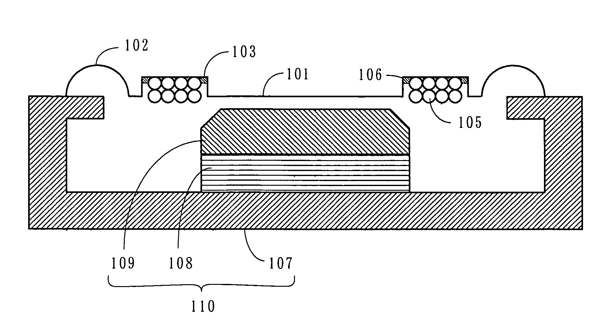
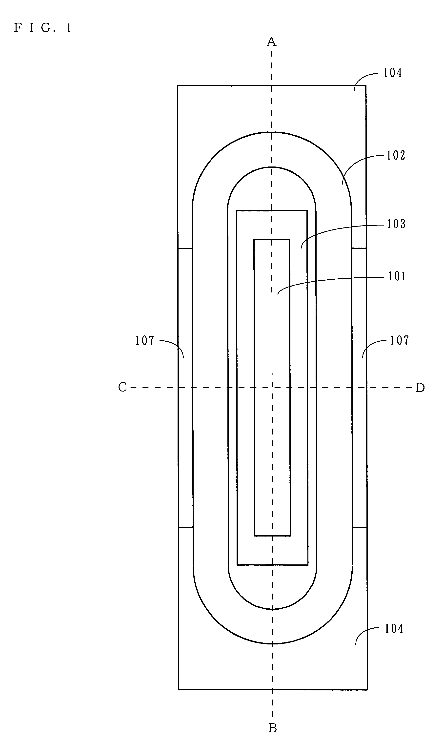
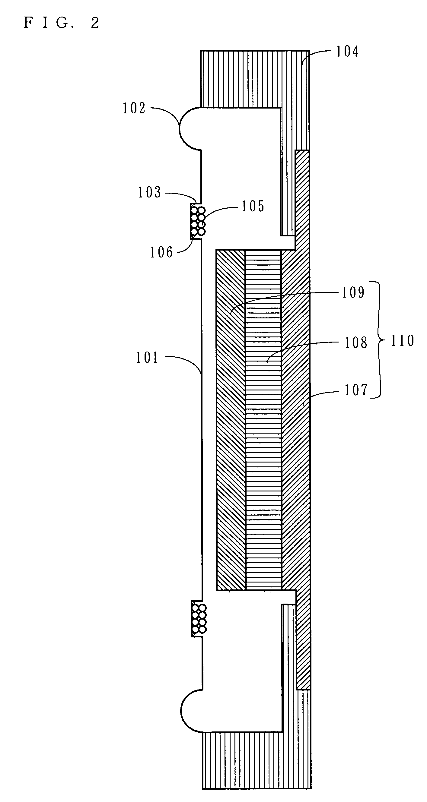
[0047]A loudspeaker according to a first embodiment of the present invention is now described. FIG. 1 is a plan view of the loudspeaker, FIG. 2 is a cross-sectional view (an A-B cross-sectional view) of the loudspeaker in a long axis direction, and FIG. 3 is a cross-sectional view (a C-D cross-sectional view) of the loudspeaker in a short axis direction. In FIGS. 1 through 3, the loudspeaker includes a diaphragm 101, an edge 102, a frame 104, a voice coil 105, a yoke 107, a magnet 108, and a top plate 109. As shown in FIG. 1, the loudspeaker has a shape which is elongated in a vertical (or horizontal) direction. Note that in the following descriptions, a side of the loudspeaker on which the diaphragm 101 is provided (the left side in FIG. 2) is referred to as an “upper surface side”, and a side on which the yoke 107 is provided (the right side in FIG. 2) is referred to as a “lower surface side”. Also, a longitudinal direction of the diaphragm 101, which is roughly planar-shaped, is ...
second embodiment
[0060]Described next is a loudspeaker according to a second embodiment. FIG. 5 is a cross-sectional view of the loudspeaker according to the second embodiment in the short axis direction. Note that the loudspeaker according to the second embodiment has an external appearance similar to that of the loudspeaker according to the first embodiment. A plan view of the loudspeaker is omitted since it is similar to FIG. 1. FIG. 5 corresponds to FIG. 3 in the first embodiment. Note that in FIG. 5, elements similar to those shown in FIGS. 1 through 3 are denoted by the same reference numerals. Hereinbelow, the loudspeaker according to the second embodiment is described mainly with respect to differences from the loudspeaker according to the first embodiment.
[0061]In the second embodiment, as in the first embodiment, the voice coil 105 is bonded to the bottom of the groove 103 of the diaphragm 101. Here, in the second embodiment, an adhesive 201 is applied so as to form an adhesive fillet cove...
third embodiment
[0062]Described next is a loudspeaker according to a third embodiment. FIGS. 6 and 7 are views showing a loudspeaker of a third embodiment. Specifically, FIG. 6 is a plan view of the loudspeaker, and FIG. 7 is a cross-sectional view of the loudspeaker in the short axis direction. Note that in FIGS. 6 and 7, elements similar to those shown in FIGS. 1 through 3 are denoted by the same reference numerals. Hereinbelow, the loudspeaker according to the third embodiment is described mainly with respect to differences from the loudspeaker according to the first embodiment.
[0063]In the third embodiment, a plurality of protrusions 301 are provided on the bottom of the groove 103 of the diaphragm 101. It is preferred that the protrusions 301 each are smaller (in height or width) than a diameter of a wire of the voice coil 105. The protrusions 301 may be regularly or irregularly placed on the bottom of the groove 103. Also, the protrusions 301 may be convex to the upper or lower surface side o...
PUM
 Abstract
Description
Claims
Application Information
 - R&D
- Intellectual Property
- Life Sciences
- Materials
- Tech Scout
- Unparalleled Data Quality
- Higher Quality Content
- 60% Fewer Hallucinations
Browse by: Latest US Patents, China's latest patents, Technical Efficacy Thesaurus, Application Domain, Technology Topic, Popular Technical Reports.
© 2025 PatSnap. All rights reserved.Legal|Privacy policy|Modern Slavery Act Transparency Statement|Sitemap|About US| Contact US: help@patsnap.com


