Method and device for data-flow protection of optical interface in data communication equipment

a data communication equipment and optical interface technology, applied in the field of data communication technology, can solve the problems of inability to reselect other routes, data flow is broken, and communication equipment becomes an isolated information island,

Active Publication Date: 2008-11-04
HUAWEI TECH CO LTD
View PDF9 Cites 2 Cited by
  • Summary
  • Abstract
  • Description
  • Claims
  • Application Information

AI Technical Summary

Benefits of technology

[0008]Objective of the invention is to propose a method and device for data-flow protection of an op

Problems solved by technology

In network environment, data-flow is broken usually because of the failure of data communication equipment, such as router, switch and etc.
1. When communication equipment is at the edge of a network and there are no redundant routes, failure of intermediate communication equipment usually makes the communication equipment become an isolated information island.
2. In some special application, the source route has been defined and reselecting other route is not allow

Method used


Image

  • Method and device for data-flow protection of optical interface in data communication equipment
  • Method and device for data-flow protection of optical interface in data communication equipment
  • Method and device for data-flow protection of optical interface in data communication equipment

Examples


Embodiment Construction

[0030]The following description of the preferred embodiments are merely exemplary in nature and is in no way intended to limit the invention, its application, or uses.

[0031]The presented invention now will be described more fully hereinafter with reference to the accompanying drawings, in which preferred embodiments of the invention are shown. This invention may, however, be embodied in many different forms and should not be construed as limited to the embodiments set forth herein; rather, these embodiments are provided so that this disclosure will be thorough and complete, and will fully convey the scope of the invention to those skilled in the art. Like numbers refer to like elements throughout.

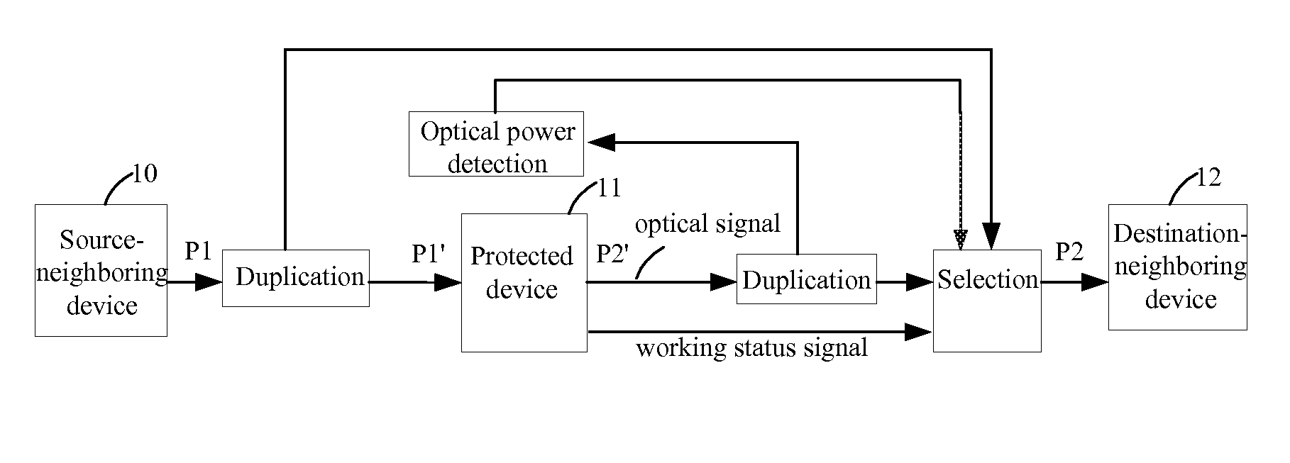
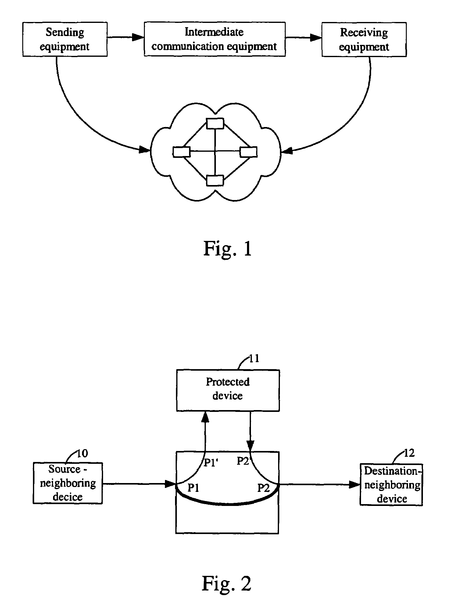
[0032]The logical diagram of the invention is shown in FIG. 2. The protected device 11, such as a router, the source-neighboring device 10 and the destination-neighboring device 12 are interconnected through the device of the invention, wherein P1, P1′, P2 and P2′ are optical interfaces. Wh...


PUM


Abstract

The invention discloses a method and device for data-flow protection of an optical interface in data communication equipment. First, receiving an optical-signal from a source-neighboring device, then duplicating the received optical signal into two duplicated optical signals. One of them is sent to a protected device for processing. According to the protected device working status, either the optical signal having been processed by the protected device or the second duplicated optical signal is selected and sent to a destination-neighboring device. The device of the invention includes a first optical-signal duplicating unit and an optical-signal selecting unit. The first optical-signal duplicating unit is used for duplicating an optical signal, and the optical-signal selecting unit is used as a selector. The method and device proposed by the invention are independent to network topology and can protect data-flow reliably. The method and device can be used for applications that are sensitive for break time or is strict for routing in order to guarantee data security.

Description

CROSS-REFERENCE TO RELATED APPLICATIONS[0001]This application claims the benefit of Chinese Patent Application No. 02126615.8 filed on Jul. 18, 2002. The disclosure of the above application is incorporated herein by reference.FIELD OF THE INVENTION[0002]The present invention relates to data communication technology, and more particularly to a method and device for data-flow protection of an optical interface in data communication equipment.BACKGROUND OF THE INVENTION[0003]In network environment, data-flow is broken usually because of the failure of data communication equipment, such as router, switch and etc. The broken data-flow can be recovered usually by the multi-path effect of a network. Based on network protocols, the data sender can discover that there is a failure in intermediate communication equipment, and a new route is reselected to bypassing the failure equipment, as shown in FIG. 1.[0004]Generally, the broken data-flow can be recovered by the multi-path effect of netwo...

Claims


Application Information

Patent Timeline
IPC IPC(8): H04B10/00H04B10/03H04B10/038H04B10/079H04B10/29
CPCH04B10/032
Inventor WANG, CHONGYANGZHANG, ZHICHUNDONG, SHUNYOU
Owner HUAWEI TECH CO LTD
Why Eureka
Try Eureka