Multilayer printed circuit board for high-speed differential signal, communication apparatus, and data storage apparatus

a printed circuit board and high-speed differential technology, applied in the field of printed circuit boards, can solve problems such as reflection noise, distortion of waveforms, and generation of reflection noise, and achieve the effect of reducing jitter

Inactive Publication Date: 2008-11-11
HITACHI LTD
View PDF6 Cites 47 Cited by
  • Summary
  • Abstract
  • Description
  • Claims
  • Application Information

AI Technical Summary

Benefits of technology

[0019]The degree of coupling between differential signal transmission lines is decreased by widening the line-spacing of the differential signal transmission lines that are connected to via holes, and jitter is accordingly decreased by decreasing the reflection of backward crosstalk due to an open-stub of a via hole. Therefore, the jitter can be suppressed to the same amount as that of a via hole with no open-stub.
[0022]Even in the case of differential signal transmission lines, the jitter is decreased by changing the degree of coupling in accordance with an open-stub length.

Problems solved by technology

However, in the case of high-speed signal transmission more than 1 GHz between the LSIs, the via hole itself causes the distortion of its waveform.
Irrespective of the fact, the distortion is caused due to difficulty of adjusting the impedance in the via holes to that of the transmission lines.
The impedance of the via hole does not match the characteristic impedance of the pulled-out transmission lines, so that reflection noise is generated due to impedance mismatch immediately before and after signals pass through the via hole.
This impedance mismatch causes the distortion of a signal waveform due to the via hole.
However, the back drill is applied to each via hole including the open-stub, which increases the steps of preparing printed circuit boards and causes a rise in cost.
Especially in a printed circuit board such as a mother board for a backplane bus, on which plural connectors are mounted, the number of via holes reaches from the thousands to the tens of thousands, which increases the cost of the back drill, and results in an increase of the cost of the apparatus.

Method used


Image

  • Multilayer printed circuit board for high-speed differential signal, communication apparatus, and data storage apparatus
  • Multilayer printed circuit board for high-speed differential signal, communication apparatus, and data storage apparatus
  • Multilayer printed circuit board for high-speed differential signal, communication apparatus, and data storage apparatus

Examples


first embodiment

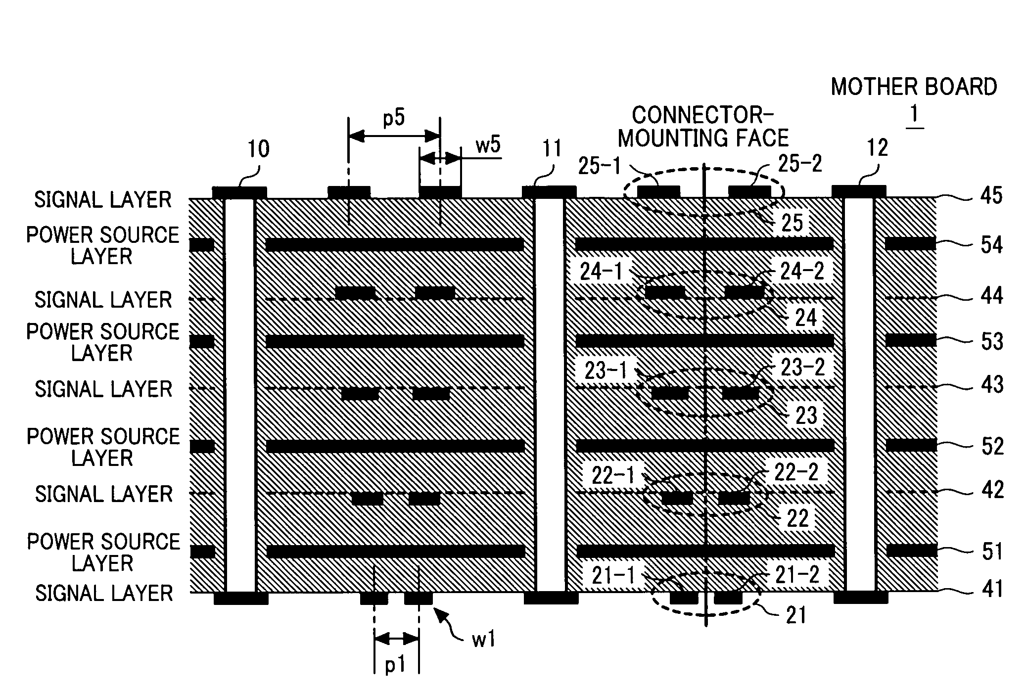
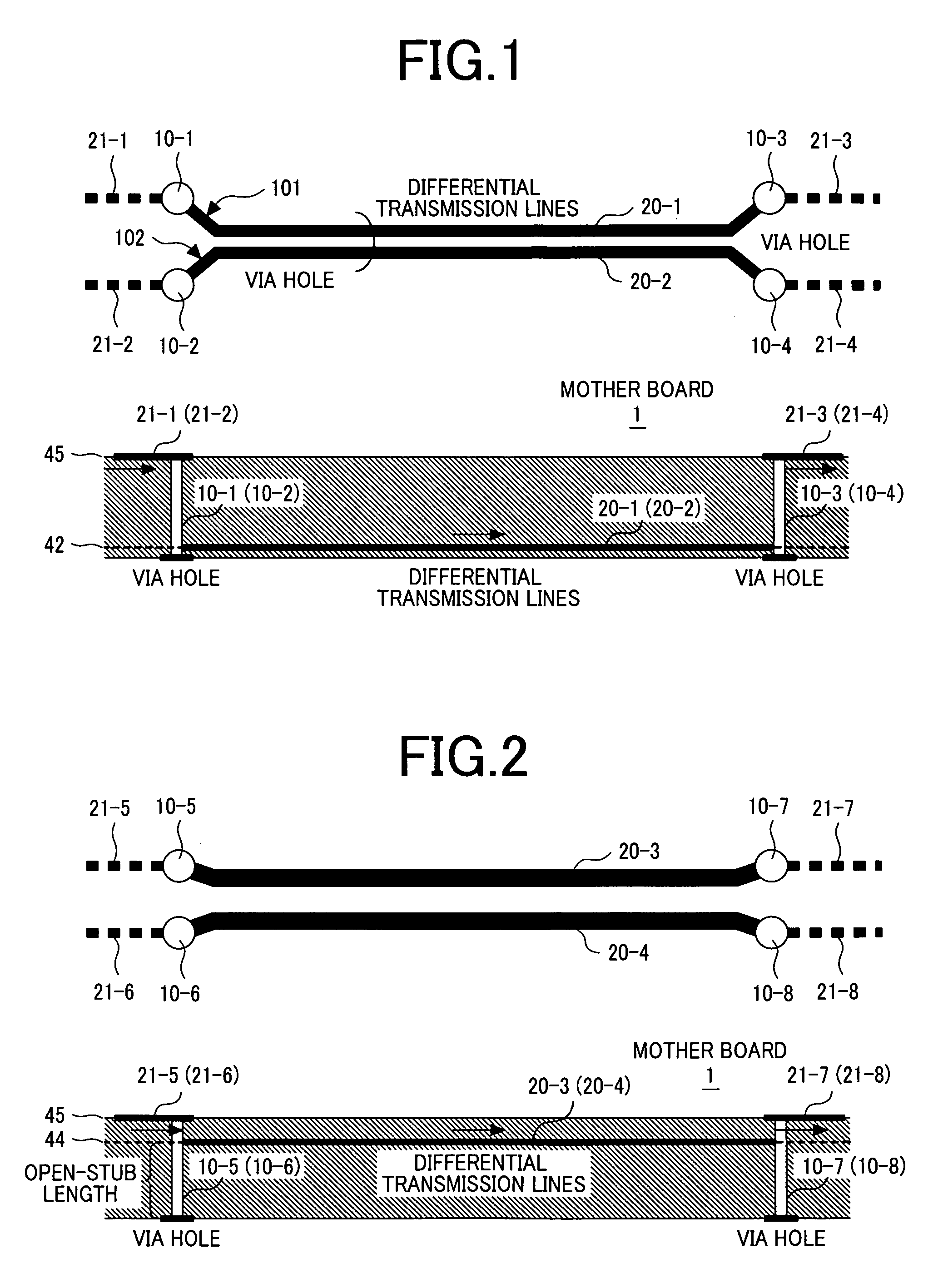
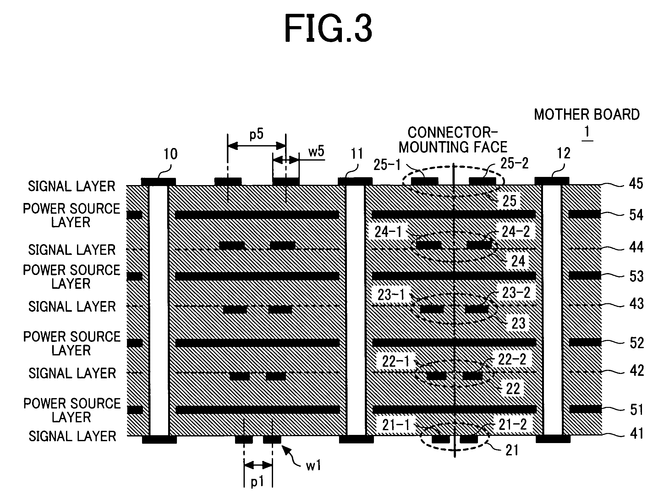
[0039]The first embodiment will be described using FIGS. 1 to 7. FIG. 1 is a plan view and a cross sectional view of a printed circuit board having via holes with a short open-stub length. FIG. 2 is a plan view and a cross sectional view of a printed circuit board having via holes with a long open-stub length. FIG. 3 is a sectional side view of a printed circuit board having layers, each having different line-spacing between transmission lines. FIG. 4 is a bird's eye perspective view of a via hole with a long open-stub length. FIG. 5 is a diagram for explaining pairs of differential transmission lines, each pair having a different degree of coupling. FIG. 6 is a diagram for explaining a signal propagation characteristic with an open-stub length as a parameter. FIG. 7 is a diagram for explaining signal jitter caused by via holes with open-stub lengths and differential transmission lines each having different line-spacing.

[0040]In FIGS. 1 and 2, a multilayer mother board 1 includes pe...

second embodiment

[0071]The second embodiment will be described using FIGS. 8 to 11. In the second embodiment, the structure of the differential signal transmission lines in the first embodiment is applied to a backplane bus. FIG. 8 is a plan view of plural printed circuit boards configuring a backplane bus. FIGS. 9 and 10 are diagrams for explaining wiring structures of connector portions. FIG. 11 is a bird's eye view of plural printed circuit boards configuring a backplane bus.

[0072]As being apparent with reference to FIG. 11, connectors 70-1 to 70-8 are mounted on a mother board 1 in FIG. 8. Daughter boards can be inserted and mounted to the connectors 70-1 to 70-8. In FIG. 8, the daughter boards 60-1, 60-4, 60-5, and 60-8 are inserted to the connectors 70-1, 70-4, 70-5, and 70-8, respectively. FIG. 8 illustrates eight connectors whereas FIG. 11 illustrates connectors of more than eight. However, the number is not essential so that the connectors are represented by 70-n in FIG. 11. On each daughte...

third embodiment

[0082]The third embodiment will be described using FIG. 12. FIG. 12 is a cross sectional view of a multilayer printed circuit board.

[0083]On the mother board 1 shown in FIG. 3, the striplines of the inner layers 42 to 44 are composed of two single-ended transmission lines 23-1 and 23-2 having an extremely low degree of coupling, that is, wide line-spacing, and strongly-coupled microstriplines 21-1 and 21-2 are arranged on the outer layers 41 and 45. All the transmission lines have the same differential impedance.

[0084]The waveform 91 in FIG. 7 represents the jitter in a system in which the wiring of the microstrip structure is connected to via holes with no open-stub lengths. Here again, it can be found that the jitter of the waveform 91 is decreased as the degree of coupling of the transmission lines becomes higher, that is, in the order of the wiring type D to A. The waveform 91 is obtained from the wiring of the wiring layers 45 and 41 in FIG. 3. Since these layers are surface la...


PUM


Abstract

In the case where high speed differential signals are transmitted in differential transmission lines through via holes with open-stubs, signal waveforms are distorted due to impedance mismatch in the open-stubs of the via holes, thus causing jitter, which has become an issue of high speed signals. For differential transmission lines that pass through via holes with open-stubs, a degree of coupling of the lines is decreased while the differential characteristic impedance is made constant. Thereby, the effects of backward cross talk noise caused by the coupling can be minimized, and thus jitter can be suppressed.

Description

CLAIM OF PRIORITY[0001]The present application claims priority from Japanese patent application Serial no. 2005-336725, filed on Nov. 22, 2005, the content of which is hereby incorporated by reference into this application.BACKGROUND OF THE INVENTION[0002]1. Field of the Invention[0003]The present invention relates to a printed circuit board, a communication apparatus, and a data storage apparatus, and particularly to a printed circuit board suitable for forming differential signal paths thereon, and a communication apparatus and a data storage apparatus using the printed circuit board.[0004]2. Description of the Related Art[0005]As a method of transmitting a signal between LSIs, there is known a serial transmission in which information is transmitted and received by connecting the LSIs to each other with the use of differential transmission lines composed of two signal transmission lines. The transmission lines which are connected between the LSIs and which are arranged on a printe...

Claims


Application Information

Patent Timeline
Patent Type & Authority Patents(United States)
IPC IPC(8): H01R12/00
CPCH01L23/49838H01L23/66H04L25/0272H04L25/0278H04L25/08H05K1/0216H05K1/0245H05K1/0251H01L23/50H01L2223/6638H01L2924/3011H05K1/0298H05K2201/0352H05K2201/044H05K2201/09236H01L2924/0002H01L2924/00
Inventor OSAKA, HIDEKI
Owner HITACHI LTD
Why Eureka
Try Eureka