Ship propulsion system with cooling systems for the stator and rotor of the synchronous machine of the propulsion system

Inactive Publication Date: 2008-11-11
SIEMENS AG
View PDF16 Cites 17 Cited by
  • Summary
  • Abstract
  • Description
  • Claims
  • Application Information

AI Technical Summary

Benefits of technology

[0057]In this way, already available water, such as the freshwater or servi

Problems solved by technology

However, the radial dimension is limited in some types of machines.
In those types of machines having a relatively small outside diameter, heat generated in the stator winding is difficult to dissipate usi

Method used


Image

  • Ship propulsion system with cooling systems for the stator and rotor of the synchronous machine of the propulsion system
  • Ship propulsion system with cooling systems for the stator and rotor of the synchronous machine of the propulsion system
  • Ship propulsion system with cooling systems for the stator and rotor of the synchronous machine of the propulsion system

Examples


Embodiment Construction

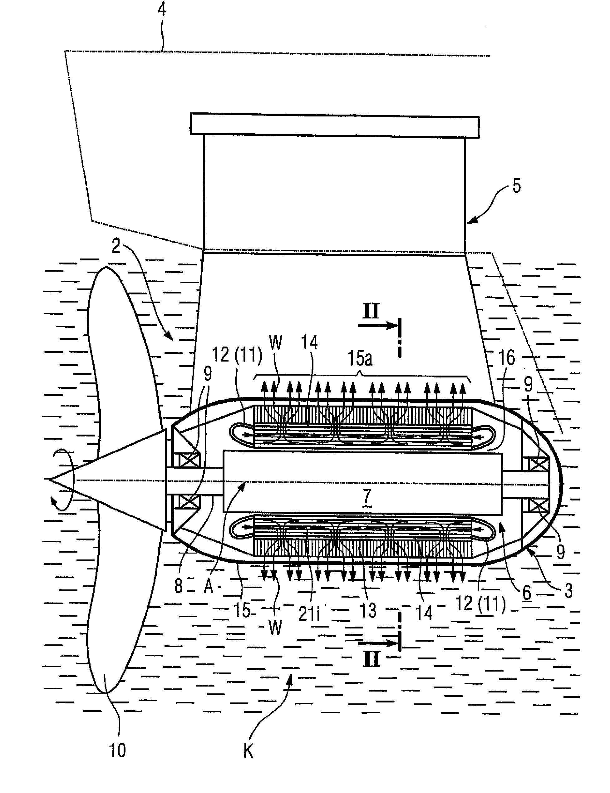
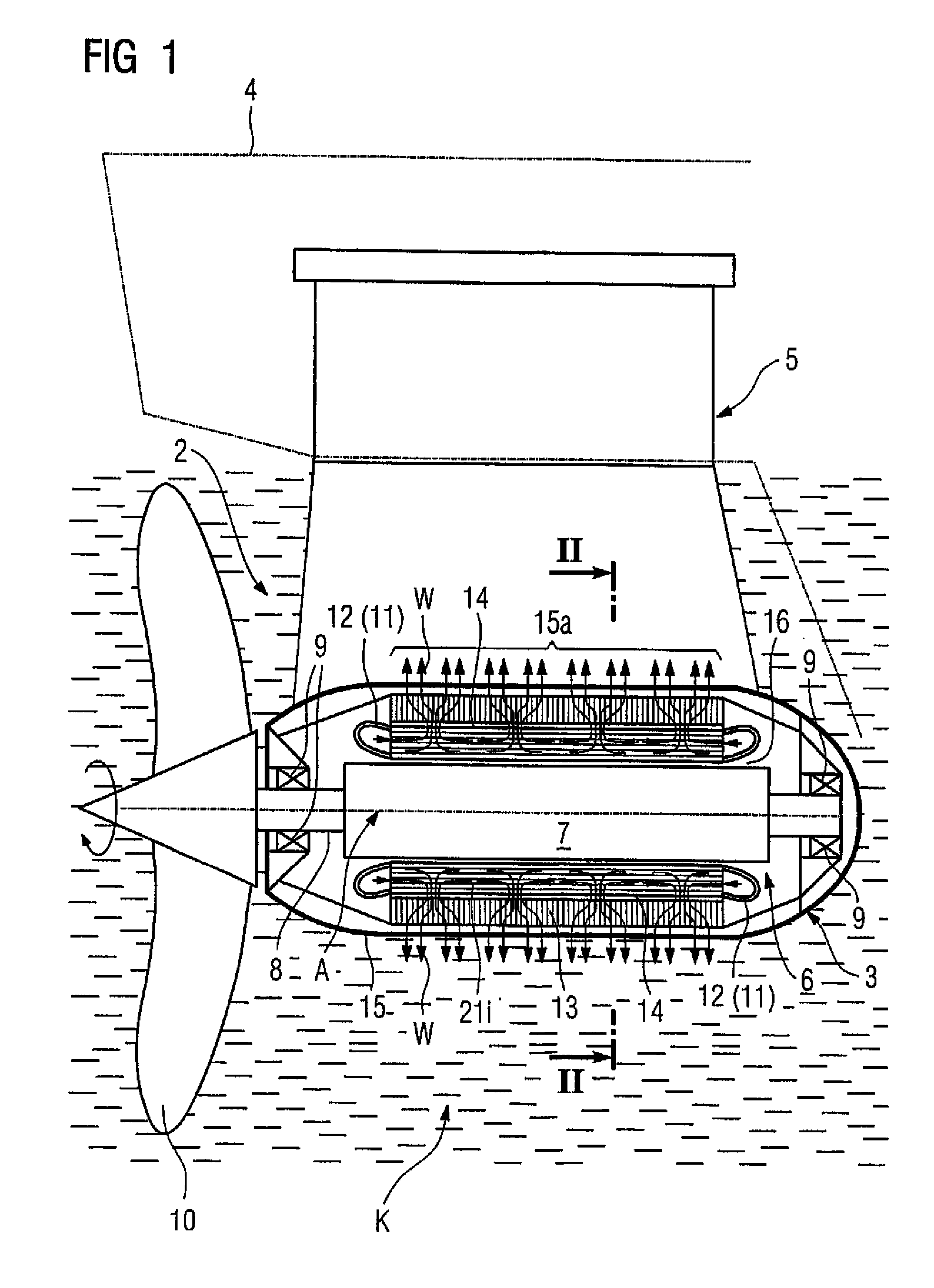
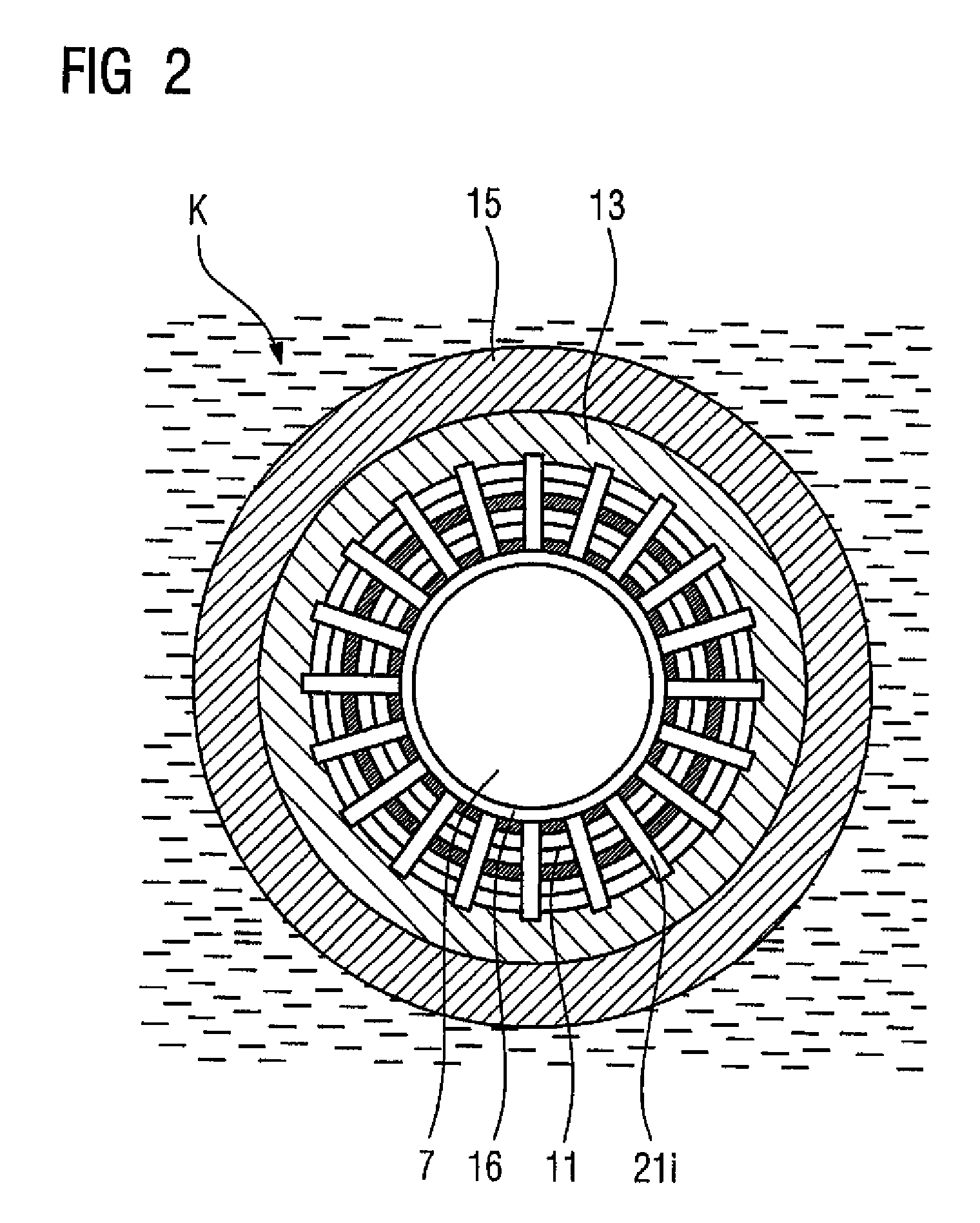
[0066]Corresponding elements in the figures are labeled with the same reference symbols.

[0067]The ship propulsion system according to the invention with at least one synchronous machine is based on conventional propulsion systems, which can be, in particular, a propulsion system of a propeller / pod type or also of a water jet type. A propeller / pod type will be assumed for the following exemplary embodiment described below. Its synchronous machine includes a rotor with a low-temperature, in particular superconducting, multi-pole rotor winding which is thermally coupled, for example directly, to a rotor cooling system. The term direct coupling is to be understood as referring to a cooling system with a cooling medium in direct thermal contact with the parts of support of winding to be cooled. However, indirect cooling is also feasible, whereby heat is transferred between the parts of the rotor winding to be cooled and a rotor cooling system or a cooling medium through solid elements. A...


PUM


Abstract

Disclosed is a ship propulsion system comprising a synchronous machine (6) with an especially superconducting rotor winding that is to be subjected to intense cooling and a normally conducting stator winding (11) which is to be cooled. The stator winding (11) is disposed at least in part inside a support structure (14) encompassing a hollow cylindrical magnetically soft outer body (13) and web-type support teeth (21i) that extend in an axial and radial direction. A hollow cylindrical part (15a) of an exterior housing (15) encloses the outer body (13). In order to cool at least some areas of said housing part (15a), the stator winding (11) is thermally coupled to water as a cooling medium (K) via the support structure (14) and the housing part (15a).

Description

BACKGROUND OF THE INVENTION [0001]The invention relates to a ship propulsion system with a synchronous machine which includes[0002]a) a rotor with a multi-pole rotor winding to be cooled to low temperatures, in particular to superconducting temperatures, wherein the rotor winding is thermally coupled directly or indirectly to a rotor cooling system, and[0003]b) a stator surrounding the rotor with[0004]a cooled, normal-conducting stator winding,[0005]a support structure which at least partially supports the stator winding, the support structure having an essentially hollow-cylindrical outer body made of a soft-magnetic material and axially and radially extending fin-shaped support teeth disposed on the inside of the support structure, with at least sections of the stator winding being arranged between the support teeth,[0006]an outside housing with a hollow-cylindrical housing section surrounding the outer body, and[0007]a stator cooling system for dissipating heat generated by the s...

Claims


Application Information

Patent Timeline
IPC IPC(8): B63H21/14B63H21/17B63H23/24H02K7/14H02K9/19H02K55/04
CPCB63H23/24H02K9/19B63H2021/173H02K7/14H02K55/04Y02T70/5263Y02T70/50H02K5/20
Inventor HUBER, NORBERTRIEGER, JURGENSCHMIDT, WOLFGANGWACKER, BERNDFRAUENHOFER, JOACHIMRZADKI, WOLFGANG
Owner SIEMENS AG
Why Eureka
Try Eureka