Method for supplying spectacle lens

a technology for spectacle lenses and frames, applied in the direction of spectacles/goggles, instruments, manufacturing tools, etc., can solve the problem that bevel-edged lenses cannot be fitted into spectacle frames upon delivery to opticians' shops, and achieve the effect of avoiding fluctuation of circumferential differences

Active Publication Date: 2008-11-11
HOYA CORP
View PDF25 Cites 15 Cited by
  • Summary
  • Abstract
  • Description
  • Claims
  • Application Information

AI Technical Summary

Benefits of technology

[0009]In the present invention, a spectacle lens is supplied by being edged so that the circumferential difference between a lens edge shape of a spectacle frame and an edged lens is always within a prescribed range by correcting a circumference correction value stored for every set of edging condition at the time of lens edging. More concretely, for instance, a difference (circumferential difference) between a three-dimensional spectacle lens edge circumference along the lens frame groove of the spectacle frame and a measured value of the three-dimensional bevel circumference along the peripheral bevel vertex of the edged spectacle lens is determined, and when the difference exceeds a prescribed range, correction is made to a circumference correction value stored for every set of edging condition so as to make the difference to be within the prescribed range. As a result, fluctuation of the circumferential difference can be avoided and the edged spectacle lens can properly be fitted to the spectacle frame. Similarly, in a case of rimless spectacle frame, fluctuation of the circumferential difference can be avoided, and the edged spectacle lens can properly be fitted to the rimless spectacle frame.

Problems solved by technology

However, in such a lens supply system, since no spectacle frame exist in the plant to be a edging center, it could happen that the bevel-edged lens cannot be fitted into a spectacle frame upon delivery to an optician's shop.

Method used


Image

  • Method for supplying spectacle lens
  • Method for supplying spectacle lens
  • Method for supplying spectacle lens

Examples


example 1

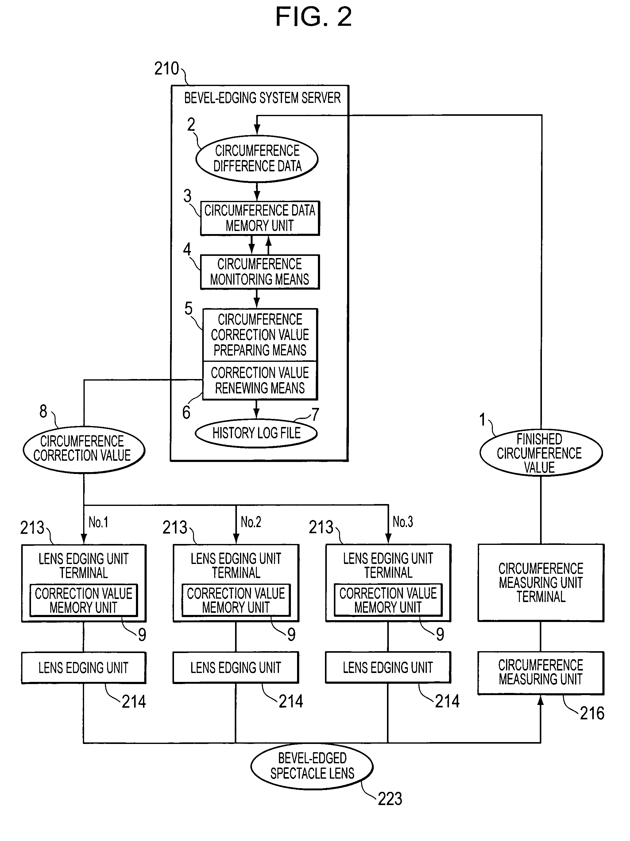
[0053]A first example in the case of renewing a circumference correction value will be explained according to FIG. 2 as Example 1.

[0054]In this example, a bevel-edging system server 210 continuously monitors whether or not circumference difference data 2 taken from a difference between the theoretical circumference, which is a component of lens edge shape data and finished circumference data 1 is in a prescribed range. The detailed explanation will be made hereinafter.

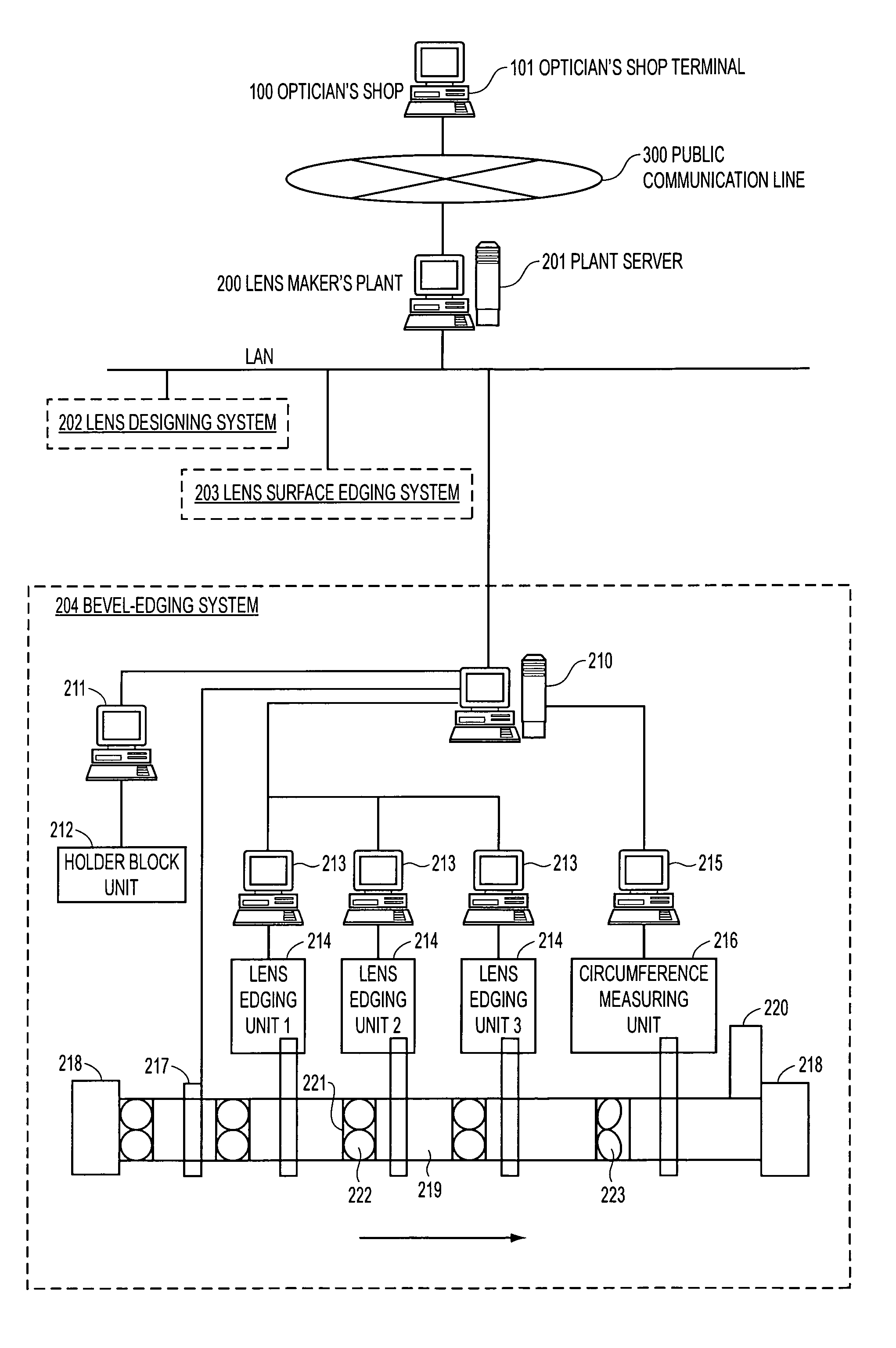
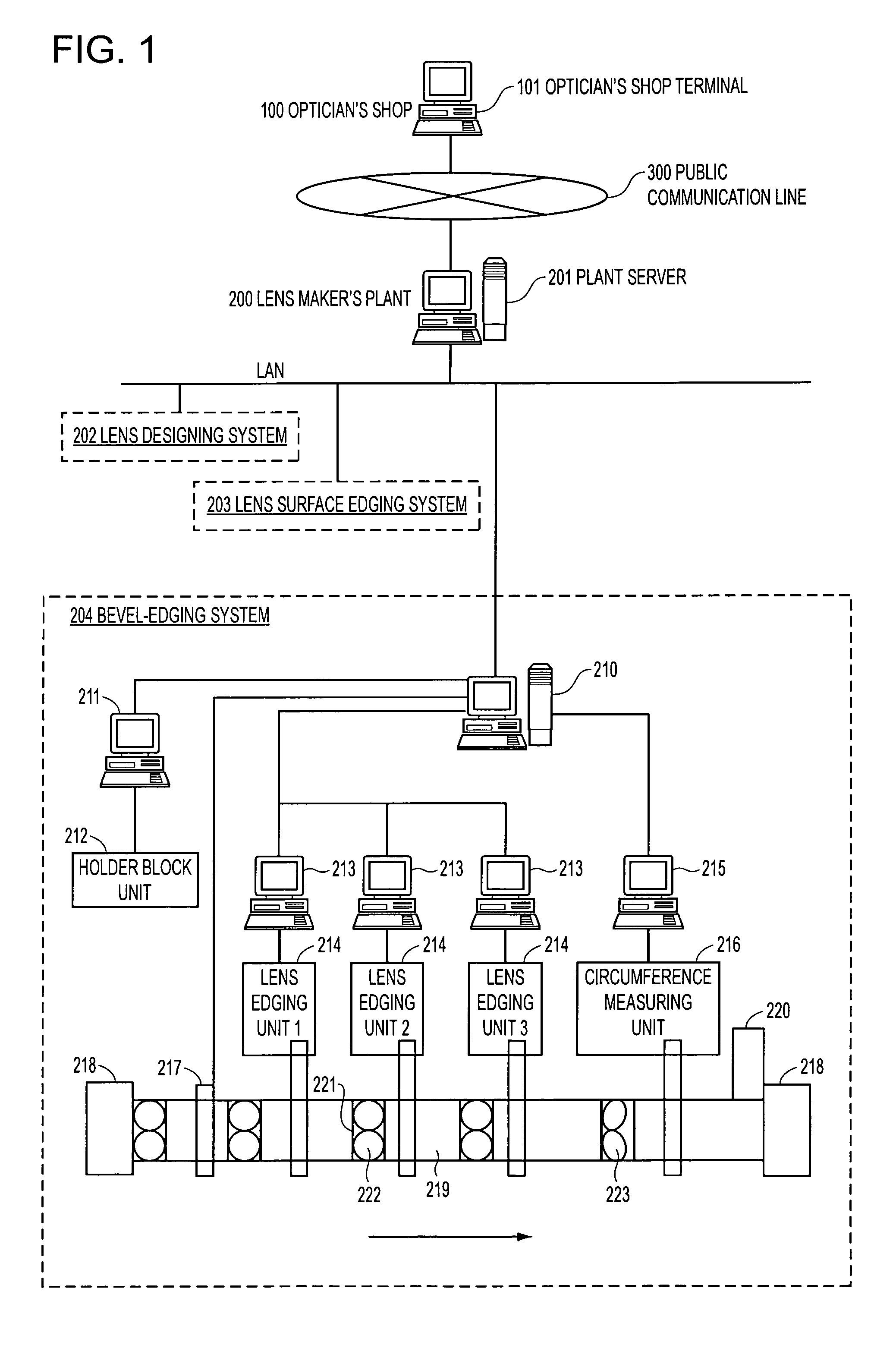
[0055]By measuring with a circumference measuring part 216 an outer periphery of a bevel-edged spectacle lens 223, which is bevel-edged by a lens edging part 214, a circumference measuring part terminal computer 215 obtains the finished circumference data 1. The circumference measuring part 216 uses a circumference measurer, described in, for instance, Japanese Patent Application Publication No. 3208566 filed by the present applicant. The finished circumference data 1 are a circumference of a spectacle lens bevel-edged...

example 2

[0081]A second example in the case of renewing a circumference correction value will be explained according to FIG. 3 as Example 2.

[0082]In this Example 2, the operator 22 himself judges whether or not a circumference difference data 2 which is a difference between the theoretical circumference and a finished circumference data 1 being one component of the lens edge shape data is within a prescribed range by continuously monitoring screen information on a display monitor 21 of the bevel-edging system server 210. On the display monitor 21, a lens edging part machine number, a set of edging conditions, a finished circumference, a difference from the theoretical circumference, pass / fail judgment result and the like are displayed for every time when edging corresponding to a job number is completed. For instance, when the pass / fail judgment result of the display monitor 21 results in “fail”, and the circumference difference data 2 is outside of the prescribed range, the operator 22 calc...


PUM

PropertyMeasurementUnit
circumferenceaaaaaaaaaa
circumference error±0aaaaaaaaaa

Abstract

Difference between a lens edge circumference and an edged lens circumference is controlled to be always within a prescribed range so that a spectacle lens of a properly finished circumference size can always be supplied.A method of supplying a spectacle lens by bevel-edging an uncut spectacle lens based on specified lens edge shape data includes a lens edging step (S2) to rim machine a spectacle lens based on a lens edge shape data and a prescribed edging condition of the spectacle frame, a lens circumference measuring step (S3) to measure the circumference of the spectacle lens bevel-edged by the lens edging step, a circumference difference calculating step (S4) to calculate difference between the lens circumference obtained by the step of measuring the lens circumference and the lens edge circumference of the spectacle frame, and a correcting step (S5 to S11) to correct the circumference correction value stored for every edging condition so as to put the circumferential difference within a prescribed range.

Description

TECHNICAL FIELD[0001]The present invention relates to a method for supplying a spectacle lens having an appropriate circumference while controlling a finished circumference of the spectacle lens in a lens edging system conducting bevel-edging of a spectacle lens based on lens edge shape data of a spectacle frame.BACKGROUND ART[0002]A spectacle lens plant receives an order of spectacle lens to be bevel-edged from optician's shops using public communication lines such as the Internet. In such a case, lens edge shape data measured with a lens edge shape measuring device (frame tracer) is transmitted from an optician's shop as data relating to the specified spectacle frame. The spectacle lens plant conducts bevel-edging of the lens based on the transmitted lens edge shape data and delivers the finished lens to the optician's shop. The optician's shop puts the bevel-edged lens into the spectacle frame and supplies the finished spectacles to the wearer.[0003]However, in such a lens supply...

Claims


Application Information

Patent Timeline
Patent Type & Authority Patents(United States)
IPC IPC(8): B24B49/00B24B1/00B24B51/00B24B9/14B24B49/02G02C7/02G02C13/00
CPCB24B49/02B24B9/148
Inventor INOGUCHI, MASAAKI
Owner HOYA CORP
Why Eureka
Try Eureka