
Polishing apparatus and polishing method

a technology for polishing apparatus and substrate, which is applied in the direction of grinding machine components, manufacturing tools, lapping machines, etc., can solve the problems of reducing the polishing speed, degrading productivity, and the conventional polishing apparatus is poorly suited for high-speed polishing, so as to improve the finish precision of the polished workpiece, improve productivity, and increase the polishing speed

Inactive Publication Date: 2008-11-11
EBARA CORP
View PDF24 Cites 2 Cited by
  • Summary
  • Abstract
  • Description
  • Claims
  • Application Information

AI Technical Summary

Benefits of technology

This configuration improves surface finish precision by eliminating edge rounding and increases polishing speed and productivity by optimizing slurry distribution and extending retainer ring service life.

Problems solved by technology

During polishing performed on the resilient polishing pad, however, excessive polishing occurred at the periphery of the workpiece, producing an effect referred to as ‘edge rounding.’ To suppress this edge rounding effect, the retainer ring was pressed against the polishing pad to flex it slightly downward at its periphery.
In conventional polishing apparatus such as described above, although pressing the retainer ring against the polishing pad solved the edge rounding problem, thus improving the surface finish precision of the polished workpiece, it also resulted in poor distribution of slurry over the surface of the workpiece being polished, which reduced polishing speed, thereby degrading productivity.
Consequently, this conventional polishing apparatus was poorly suited for high-speed polishing, which requires that a large amount of slurry be supplied to the surface being polished.
When such a fixed abrasive is used for polishing in a conventional polishing apparatus, however, because the retainer ring is now being pressed against a fixed abrasive, the ring wears faster, and the shorter retainer ring service life causes a corresponding increase in cost.

Method used


Image

  • Polishing apparatus and polishing method
  • Polishing apparatus and polishing method
  • Polishing apparatus and polishing method

Examples


Embodiment Construction

[0024]The best mode for implementing the present invention is described below, with reference to the drawings. For the purposes of this description, when the same item or an equivalent item appears in more than one figure, it is assigned the same number in all drawings in which it appears, and the description of that item is not repeated.

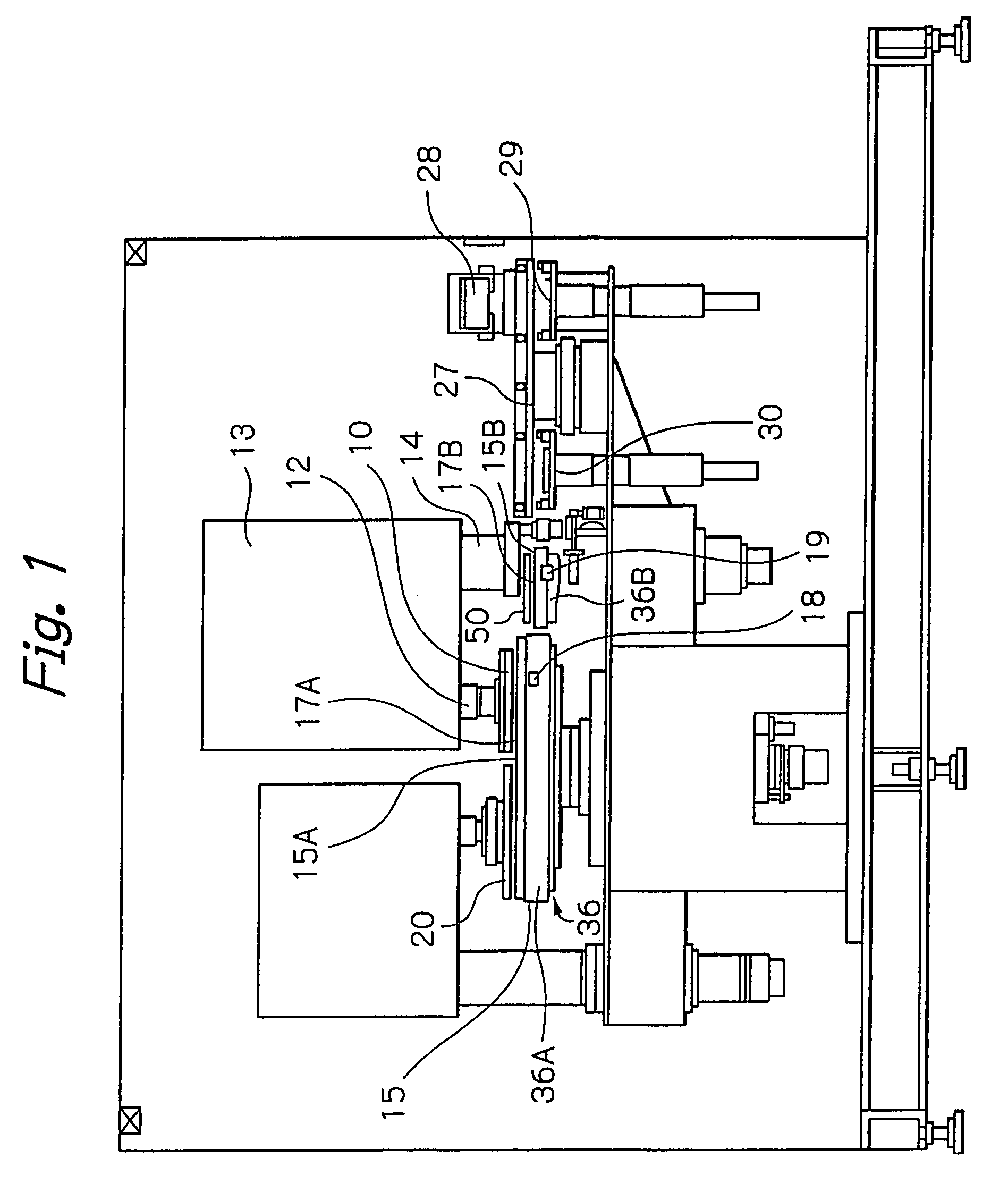
[0025]FIG. 1 shows an exterior view of a polishing apparatus 1 in this embodiment of the present invention. The configuration of this polishing apparatus will now be described, with reference to FIG. 1.

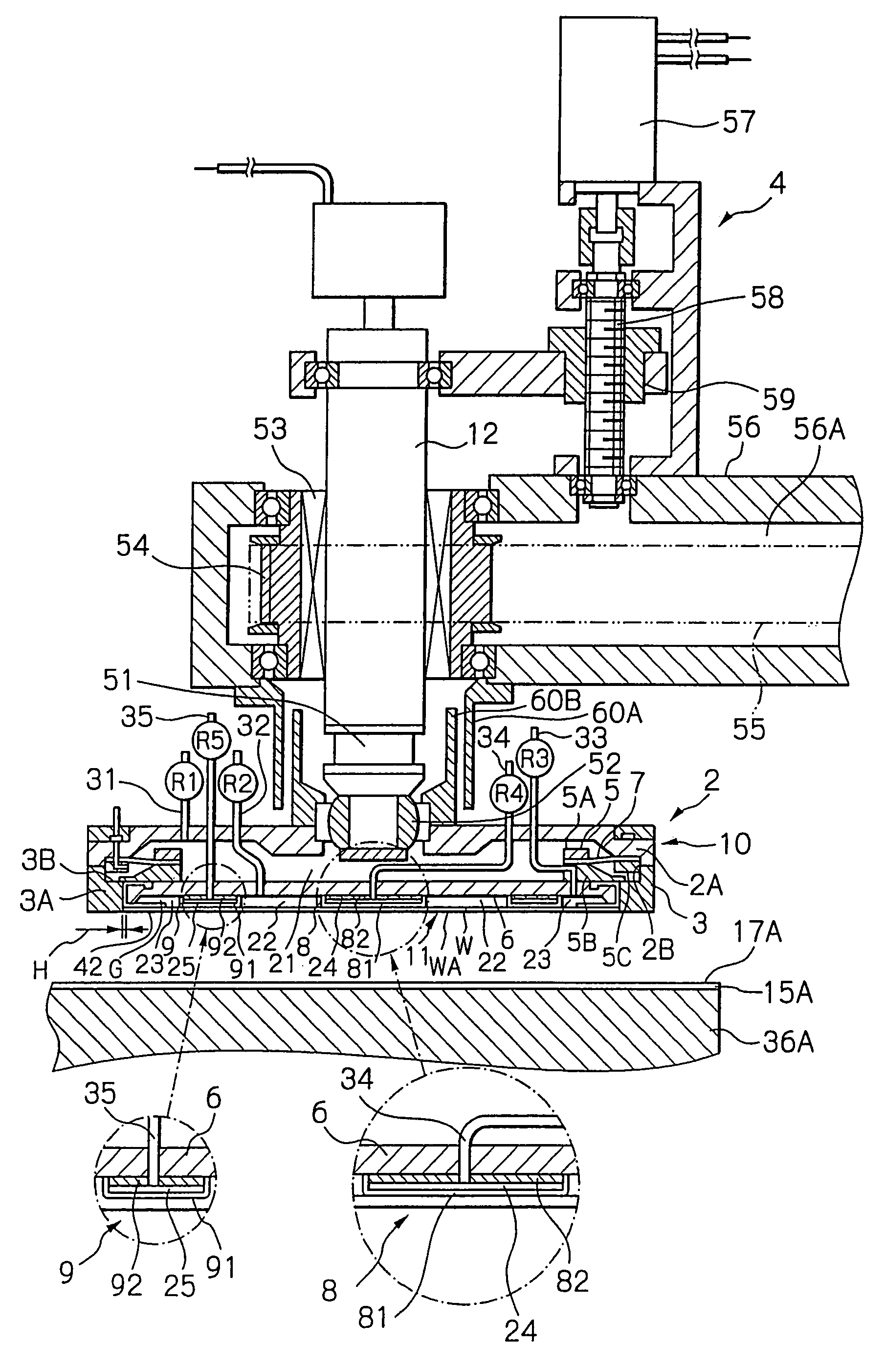
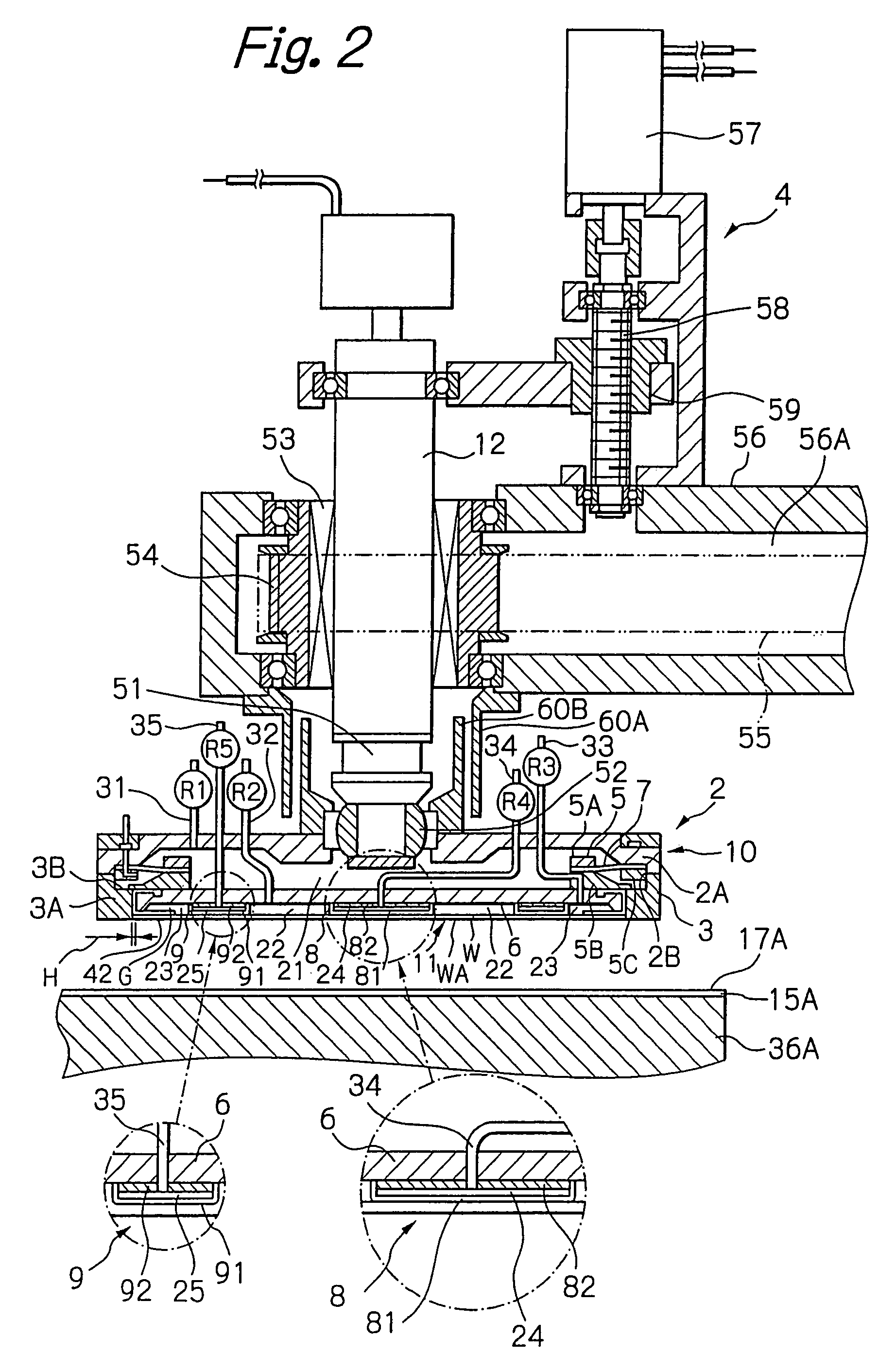
[0026]The polishing apparatus 1 comprises a substrate carrier 10 for holding a substrate S, a carrier drive shaft 12 for driving the substrate carrier 10 in rotation, a carrier head 13 that supports the carrier drive shaft 12 and a pivotal shaft 14. The pivotal shaft 14 pivots with its own axis as the center of motion, thereby causing a similar pivoting of the carrier head 13 and substrate carrier 10.

[0027]The polishing apparatus 1 also comprises a po...


PUM


Abstract

A polishing apparatus comprises a first polishing table having a first polishing surface, a substrate carrier for holding a substrate and positioning the substrate so as to bring a surface of the substrate into contact with the first polishing surface, a pressing mechanism for pressing, against the first polishing surface, the surface of the substrate which has been brought into contact with the first polishing surface by the substrate carrier, a retainer ring mounted on the substrate carrier so as to surround the substrate which has been pressed against the first polishing surface by the pressing mechanism, and a retainer-ring-position-adjustment mechanism for adjustably positioning the retainer ring relative to the substrate, which has been pressed against the first polishing surface, in directions toward and away from the first polishing surface.

Description

[0001]This is a divisional application of Ser. No. 10 / 477,533, filed May 3, 2004, now U.S. Pat. No. 7,217,175 which is the National Stage of International Application No. PCT / JP02 / 05196, filed May 29, 2002.BACKGROUND OF THE INVENTION[0002]1. Field of the Invention[0003]The present invention relates to an apparatus for performing planarization polishing of a substrate, and in particular to an apparatus for performing chemical-mechanical polishing of a substrate such as a semiconductor wafer, for planarizing the substrate.[0004]2. Background Art[0005]In earlier polishing apparatus, a substrate to be polished was held on the lower surface of a substrate carrier. Then, to polish the substrate, it was pressed against a polishing pad as a polishing slurry was supplied to the polishing surface of the pad, while establishing a relative motion between the substrate and the polishing pad. The substrate carrier was provided with a retainer ring to prevent the substrate from being dislodged fro...

Claims


Application Information

Patent Timeline
Patent Type & Authority Patents(United States)
IPC IPC(8): B24B49/00B24B1/00B24B51/00B24B37/04B24B37/30B24B37/32H01L21/304H01L21/321
CPCB24B37/30H01L21/3212B24B37/04B24B37/32H01L21/304
Inventor TOGAWA, TETSUJI
Owner EBARA CORP
Learn More