Transmission device and electronic apparatus with self-diagnostic function, and self-diagnostic method for use therein

a technology of transmission device and electronic apparatus, which is applied in the direction of digital transmission, pulse technique, local circuit, etc., can solve the problems of extremely high transfer speed and extremely high test cos

Inactive Publication Date: 2008-11-11
SILICON LIBRARY
View PDF16 Cites 6 Cited by
  • Summary
  • Abstract
  • Description
  • Claims
  • Application Information

AI Technical Summary

Benefits of technology

[0016]Therefore, the present invention aims to provide a transmission device and an electronic apparatus that are capable of making a diagnosis of their own performance without using any expensive tester, according to a communication standard for transmitting data signals and a clock signal in one direction to a reception device, and the present invention also aims to provide a self-diagnostic method for use in the same transmission device and electronic apparatus.

Problems solved by technology

In the above standards, however, the transmission data is transferred at extremely high speed, and therefore the diagnostic tester is also required to operate at high speed.
Incorporating functions for allowing the tester to operate at high speed and with high accuracy makes the tester extremely expensive.

Method used


Image

  • Transmission device and electronic apparatus with self-diagnostic function, and self-diagnostic method for use therein
  • Transmission device and electronic apparatus with self-diagnostic function, and self-diagnostic method for use therein
  • Transmission device and electronic apparatus with self-diagnostic function, and self-diagnostic method for use therein

Examples


first embodiment

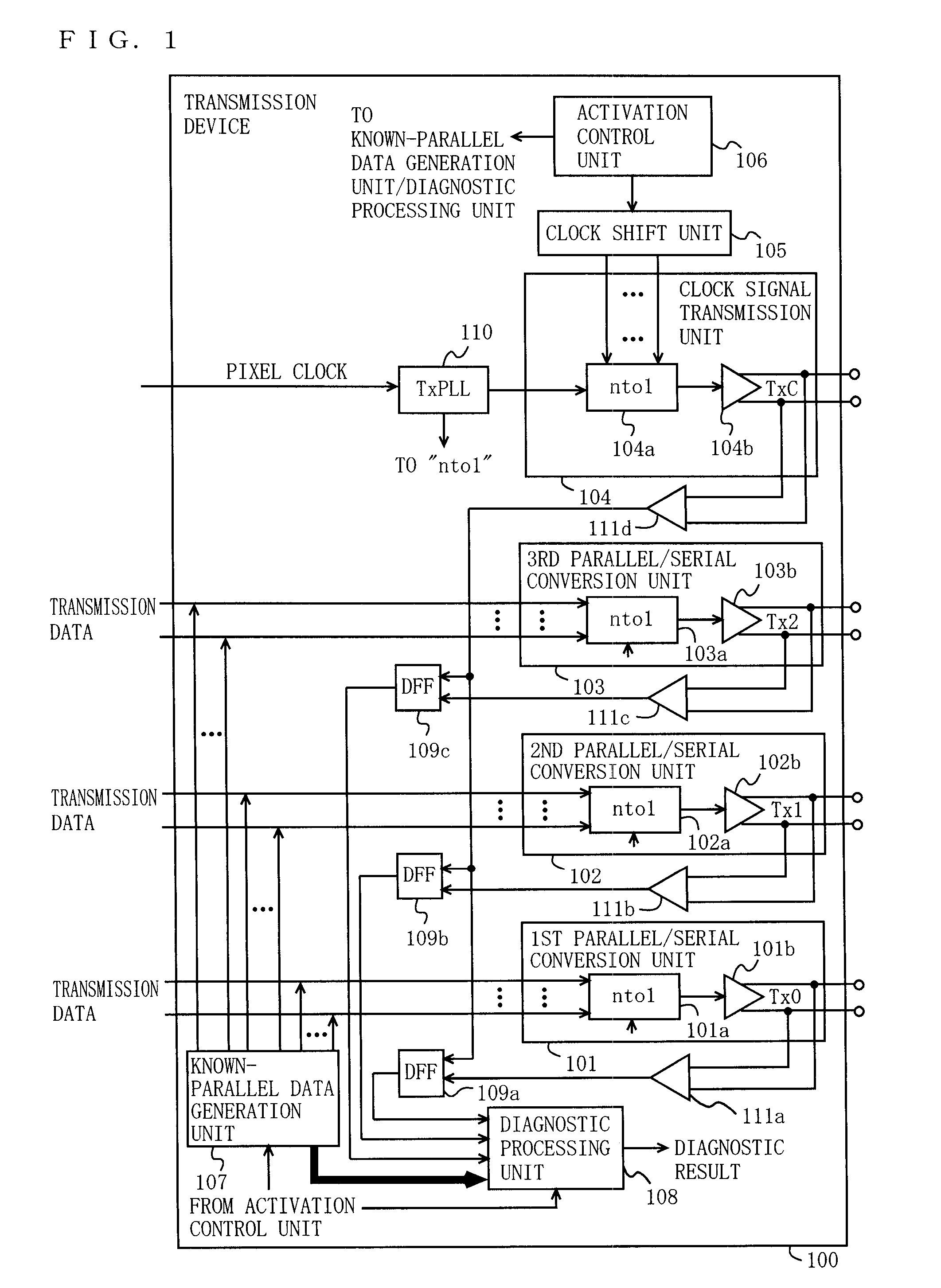
[0057]FIG. 1 is a block diagram illustrating the functional configuration of a transmission device 100 according to a first embodiment of the present invention. In FIG. 1, the transmission device 100 includes first through third parallel / serial conversion units 101, 102, and 103, a clock signal transmission unit 104, a clock shift unit 105, an activation control unit 106, a known-parallel data generation unit 107, a diagnostic processing unit 108, delay flip-flops (DFFs) 109a, 109b, and 109c, a transmission phase-locked loop circuit (TxPLL) 110, and receivers 111a, 111b, 111c, and 111d. The first parallel / serial conversion unit 101 includes a parallel / serial converter (labeled “nto1” in the figure (like elements are labeled similarly)) 101a, and a differential output circuit 101b. The second parallel / serial conversion unit 102 includes a parallel / serial converter 102a, and a differential output circuit 102b. The third parallel / serial conversion unit 103 includes a parallel / serial co...

second embodiment

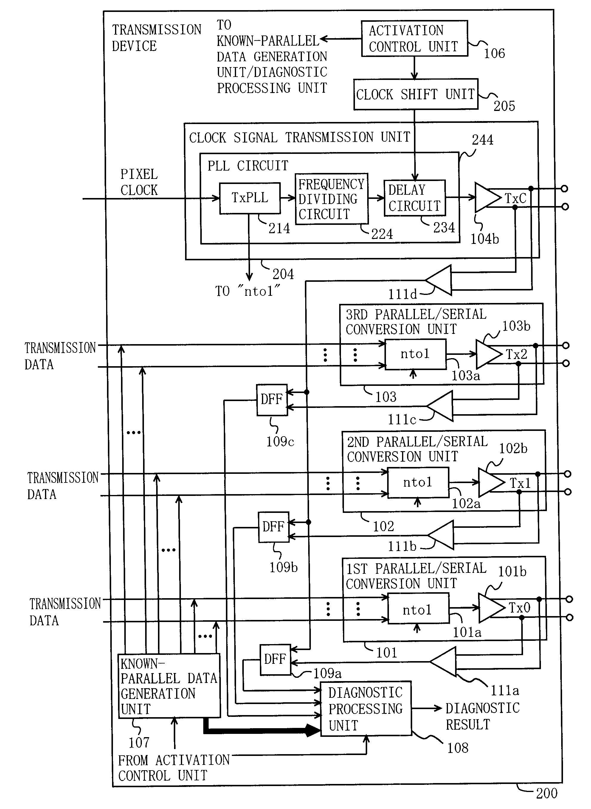
[0089]FIG. 4 is a block diagram illustrating the functional configuration of a transmission device 200 according to a second embodiment of the present invention. In FIG. 4, elements having similar functions to those in the first embodiment are denoted by the same reference numerals, and the descriptions thereof will be omitted. The second embodiment differs from the first embodiment in terms of the configuration for shifting the clock signal by 1 UI.

[0090]In FIG. 4, the clock signal transmission unit 204 includes a PLL circuit 244, and a differential output circuit 104b. The PLL circuit 244 includes a TxPLL 214, a frequency dividing circuit 224, and a delay circuit 234. The TxPLL 214 increases the frequency of the pixel clock n-fold. The frequency dividing circuit 224 reduces the frequency of the output from the TxPLL 214 to 1 / n. The delay circuit 234 delays the output of the frequency dividing circuit 224 under the control of the clock shift unit 205. When instructed by the activat...

third embodiment

[0098]In a third embodiment of the present invention, the transmission device is configured similarly to those in the first and second embodiments, and therefore FIG. 1 or 4 will be referenced. In the first and second embodiments, the clock signal TxC is shifted by 1 UI, but in the third embodiment, the clock signal TxC is continuously or gradually shifted by 1 UI within a predetermined period (e.g., a period in which jitter tends to occur, such as a period in which the data signal rises or falls).

[0099]FIG. 7 is a schematic diagram for explaining the operation of the transmission device according to the third embodiment. The transmission data (here, Tx0 is taken as an example) has jitter at its rising edge (or falling edge). In the absence of jitter (indicated by bold doted lines in the figure), the transmission device can ideally make a self-diagnosis. However, in the presence of jitter (indicated by thin lines on the figure), even if the sampling results are consistent with the k...


PUM


Abstract

A transmission device includes: parallel / serial conversion units; a clock signal transmission unit; a known-parallel data generation unit for inputting known-parallel data to the parallel / serial conversion units; a clock shift unit for sequentially shifting a clock signal, which is outputted from the clock signal transmission unit, by 1 UI of a data signal; sampling units for sampling data signals obtained by serializing the known-parallel data, in accordance with the clock signal shifted by 1 UI; and a diagnostic processing unit for making a diagnosis as to whether the transmission device is operating normally by comparing sampling results with the known-parallel data, and outputting a result of the diagnosis.

Description

BACKGROUND OF THE INVENTION[0001]1. Field of the Invention[0002]The present invention relates to transmission devices and electronic apparatuses for transmitting data signals and a clock signal, which is used on the reception device side to reproduce the data signals, in one direction to a reception device. More particularly, the present invention relates to a transmission device and an electronic apparatus with a self-diagnostic function for making a diagnosis as to whether the device / apparatus itself is operating normally, and also to a self-diagnostic method for use therein.[0003]2. Description of the Background Art[0004]In recent years, DVI (Digital Visual Interface), HDMI (High Definition Multimedia Interface), and LVDS (Low Voltage Differential Signaling) have been employed as display interface standards. In these standards, the transmission device transmits, to the reception device, data signals and a clock signal in the form of digital signals without any modification. The r...

Claims


Application Information

Patent Timeline
Patent Type & Authority Patents(United States)
IPC IPC(8): H03M9/00
CPCH03K5/135H03M9/00
Inventor YOSHIZAKI, SHOICHI
Owner SILICON LIBRARY
Why Eureka
Try Eureka