
Method and apparatus for reducing heat absorption around solder pads on an electrical lead suspension

a technology of electrical lead suspension and solder pad, which is applied in the manufacture of final products, instruments, record information storage, etc., can solve the problems of not being able to reduce the power requirement to a minimum level, most computing systems are not operational, and the electrical lead suspension is not suitable for use. , to achieve the effect of reducing heat absorption and reducing heat absorption with respect to the base metal layer

Active Publication Date: 2008-11-11
WESTERN DIGITAL TECH INC
View PDF24 Cites 23 Cited by
  • Summary
  • Abstract
  • Description
  • Claims
  • Application Information

AI Technical Summary

Benefits of technology

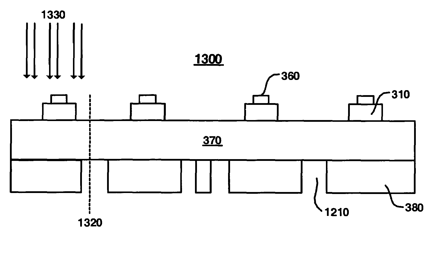
[0008]An apparatus and method for reducing heat absorption around solder pads on an electrical lead suspension (ELS). The method provides a base-metal layer having at least one opening. A dielectric layer is also provided above the base-metal layer, the dielectric layer covering a portion of the base-metal layer and at least one of the openings in the base-metal layer. A signal conductive layer is provided above dielectric layer. The signal conductive layer carries at least one solder pad portion, wherein the solder pad portion is placed above the portion of the dielectric layer such that the solder pad portion does not align with the at least one opening in the base-metal layer. In so doing, the heat absorption with respect to the base-metal layer is reduced.

Problems solved by technology

In fact, most computing systems are not operational without some type of hard disk drive to store the most basic computing information such as the boot operation, the operating system, the applications, and the like.
However, the decreased track spacing and the overall reduction in HDD component size and weight have resulted in problems with respect to the electrical lead suspension (ELS).
However, the power requirements can only be reduced to a minimum level.

Method used


Image

  • Method and apparatus for reducing heat absorption around solder pads on an electrical lead suspension
  • Method and apparatus for reducing heat absorption around solder pads on an electrical lead suspension
  • Method and apparatus for reducing heat absorption around solder pads on an electrical lead suspension

Examples


Embodiment Construction

[0028]Reference will now be made in detail to the alternative embodiment(s)s of the present invention, an apparatus and method for reducing heat absorption around solder pads on an electrical lead suspension (ELS). While the invention will be described in conjunction with the alternative embodiment(s), it will be understood that they are not intended to limit the invention to these embodiments. On the contrary, the invention is intended to cover alternatives, modifications and equivalents, which may be included within the spirit and scope of the invention as defined by the appended claims.

[0029]Furthermore, in the following detailed description of the present invention, numerous specific details are set forth in order to provide a thorough understanding of the present invention. However, it will be recognized by one of ordinary skill in the art that the present invention may be practiced without these specific details. In other instances, well known methods, procedures, components, ...


PUM

PropertyMeasurementUnit
diameteraaaaaaaaaa
diametersaaaaaaaaaa
sizeaaaaaaaaaa

Abstract

An apparatus and method for reducing heat absorption around solder pads on an electrical lead suspension (ELS). The method provides a base-metal layer having at least one opening. A dielectric layer is also provided above the base-metal layer, the dielectric layer covering a portion of the base-metal layer and at least one of the openings in the base-metal layer. A signal conductive layer is provided above dielectric layer. The signal conductive layer carries at least one solder pad portion, wherein the solder pad portion is placed above the portion of the dielectric layer such that the solder pad portion does not align with the at least one opening in the base-metal layer. In so doing, the heat absorption with respect to the base-metal layer is reduced.

Description

TECHNICAL FIELD[0001]The present invention relates to the field of hard disk drive development, and more particularly to an apparatus and method reducing heat absorption around solder pads on an electrical lead suspension (ELS).BACKGROUND ART[0002]Hard disk drives are used in almost all computer system operations. In fact, most computing systems are not operational without some type of hard disk drive to store the most basic computing information such as the boot operation, the operating system, the applications, and the like. In general, the hard disk drive is a device which may or may not be removable, but without which the computing system will generally not operate.[0003]The basic hard disk drive model was established approximately 50 years ago and resembles a phonograph. That is, the hard drive model includes a storage disk or hard disk that spins at a standard rotational speed. An actuator arm with a suspended slider is utilized to reach out over the disk. The arm carries a he...

Claims


Application Information

Patent Timeline
Patent Type & Authority Patents(United States)
IPC IPC(8): G11B21/16G11B5/48
CPCG11B5/4846H05K1/0201H05K1/111G11B5/486G11B5/4853H05K1/056H05K2201/062H05K2201/0969H05K3/3494Y02P70/50
Inventor ARYA, SATYA PRAKASHXING, XINZHI
Owner WESTERN DIGITAL TECH INC
Learn More