Phase detection method, memory control method, and related device

a phase detection and control method technology, applied in the direction of digital storage, measurement devices, instruments, etc., can solve the problem that the data strobe signal dqs may not meet a particular specification

Active Publication Date: 2008-11-11
NAN YA TECH
View PDF3 Cites 16 Cited by
  • Summary
  • Abstract
  • Description
  • Claims
  • Application Information

AI Technical Summary

Problems solved by technology

In some situations, for example, a situation where the frequency of the clock signal VCLK is increased and the signal delay of some portions within a circuit system is not properly corrected, the data strobe signal DQS may not comply with a particular specification.

Method used


Image

  • Phase detection method, memory control method, and related device
  • Phase detection method, memory control method, and related device
  • Phase detection method, memory control method, and related device

Examples


Embodiment Construction

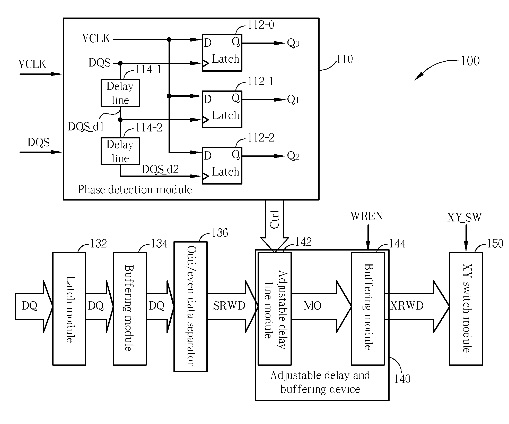
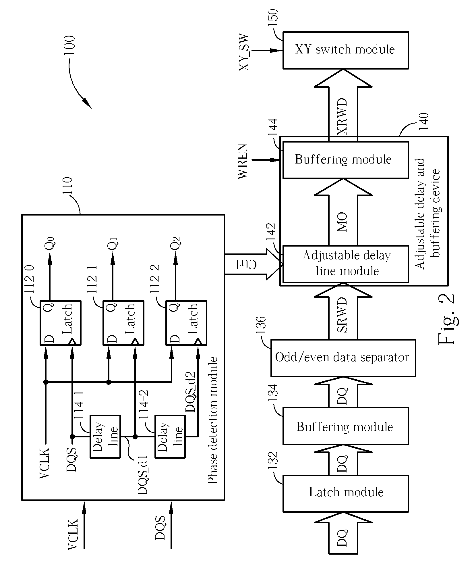
[0021]Please refer to FIG. 2. FIG. 2 is a diagram of a memory control circuit 100 according to a preferred embodiment of the present invention, where the memory control circuit 100 comprises a phase detection module 110, a latch module 132, a buffering module 134, an odd / even data separator 136, an adjustable delay and buffering device 140, and a switch module, where the adjustable delay and buffering device 140 comprises an adjustable delay line module 142 and a buffering module 144, and the switch module in this embodiment is the XY switch module 150. As shown in FIG. 2, the phase detection module 110 comprises a plurality of latches 112-0, 112-1, and 112-2 and a plurality of delay lines 114-1 and 114-2, where each delay line comprises a plurality of delay units (not shown).

[0022]The phase detection module 110 is capable of detecting a phase difference between the data strobe signal DQS and the clock signal VCLK mentioned above. Within the phase detection module 110 shown in FIG. ...


PUM


Abstract

A phase detection method for detecting a phase difference between a data strobe signal and a clock signal, includes: latching the clock signal according to the data strobe signal to generate a phase lead / lag detection result; delaying the data strobe signal to generate a plurality of delayed data strobe signals; latching the clock signal according to the delayed data strobe signals to generate a plurality of phase detection results corresponding to the delayed data strobe signals, respectively; and if the phase lead / lag detection result indicates that the data strobe signal leads the clock signal, utilizing the phase detection results to represent the phase difference between the data strobe signal and the clock signal. A memory control method and a memory control circuit respectively corresponding to the phase detection method are further provided.

Description

BACKGROUND OF THE INVENTION[0001]1. Field of the Invention[0002]The present invention relates to random access memory (RAM) control, and more particularly, to phase detection methods, memory control methods, and related devices.[0003]2. Description of the Prior Art[0004]As information technology industries develop, semiconductor component technologies progress rapidly. In order to increase the writing or reading speed of random access memories (RAMs), double data rate (DDR) technology is introduced for related applications, where RAMs utilizing DDR technology can be referred to as DDR RAMs.[0005]The data accessing of conventional RAMs corresponds to a specific edge of each of a plurality of periods of a clock signal. For example, the specific edge is a rising edge. As the data accessing of DDR RAMs corresponds to the rising and falling edges of each of a plurality of periods of a clock signal, the data accessing speed of DDR RAMs is twice as fast as the data accessing speed of conve...

Claims


Application Information

Patent Timeline
Patent Type & Authority Patents(United States)
IPC IPC(8): G11C7/00G01R29/00G11C8/00G11C8/18
CPCG11C7/22G11C7/222
Inventor CHENG, WEN-CHANG
Owner NAN YA TECH
Why Eureka
Try Eureka