
Fast motion vector prediction method

Inactive Publication Date: 2008-11-11
SONY CORP +1
View PDF3 Cites 14 Cited by
  • Summary
  • Abstract
  • Description
  • Claims
  • Application Information

AI Technical Summary

Benefits of technology

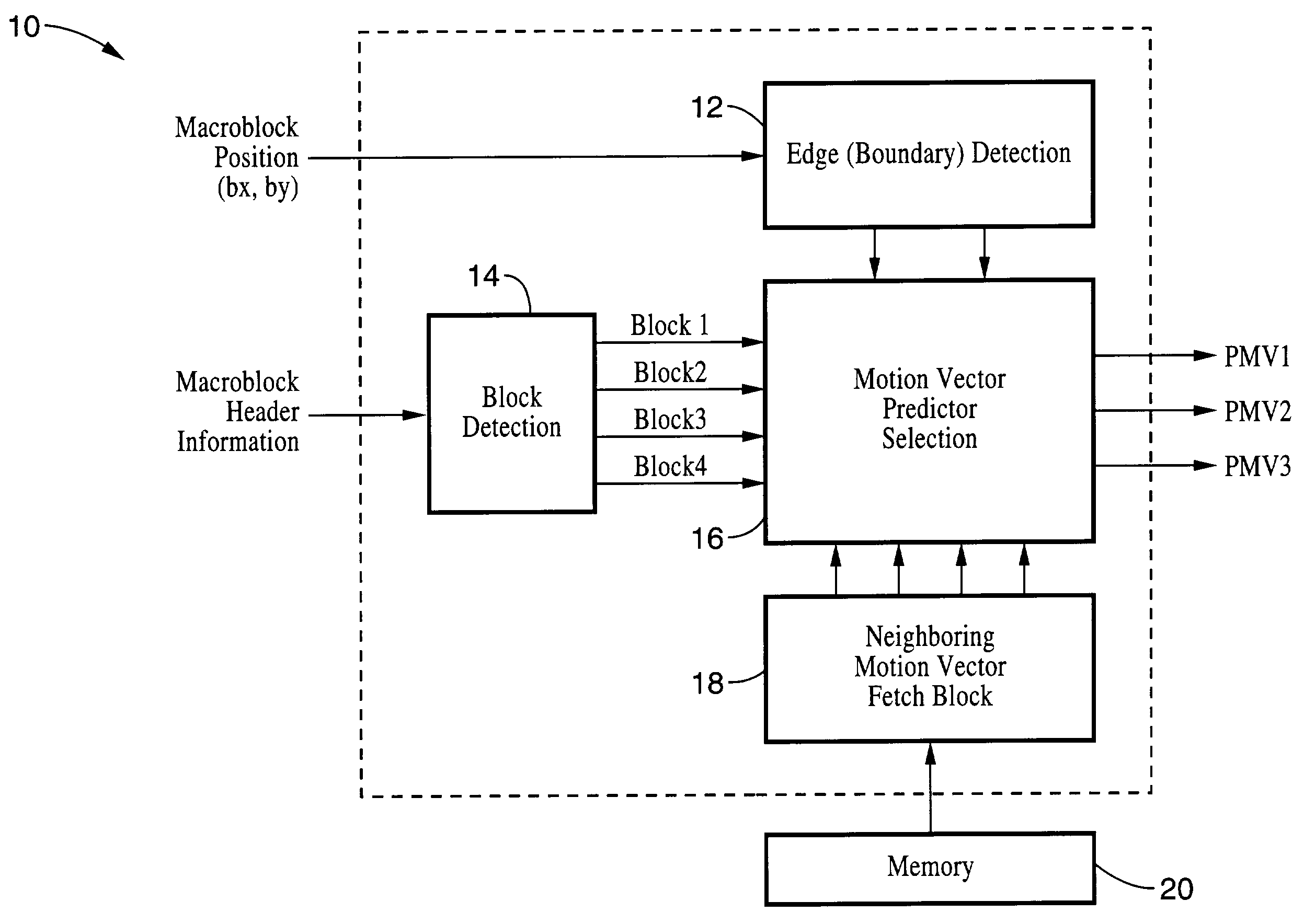
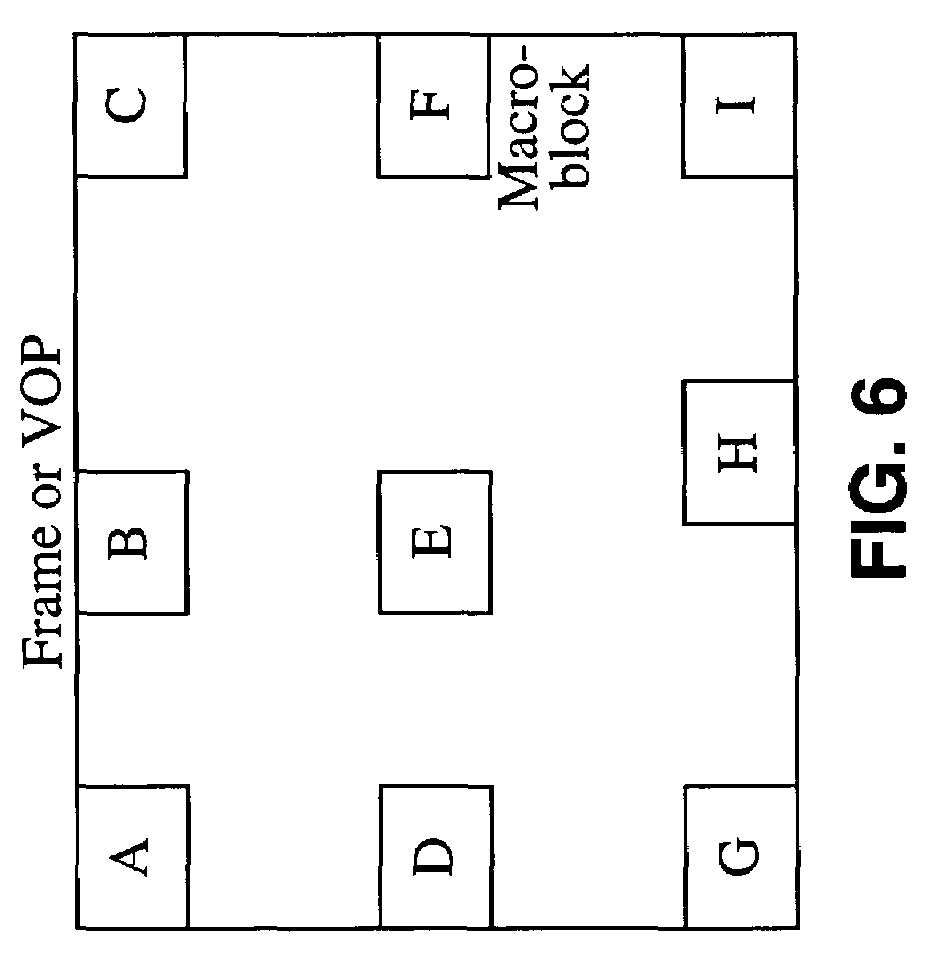
[0018]A fast prediction method is described which may be implemented cost-effectively in hardware, software, or in combinations thereof, to arrive at predictions in less time than conventional prediction methods allow. The methods described may be utilized within decoders and / or decoders utilizing any convenient protocol and is well suited for use within MPEG-4 and H.263 video coding standards. The method first categorizes the position of the macroblock in relation to its vertical and horizontal position. By way of example, the positions may be categorized in relation to whether the macroblocks are proximal to an edge of the video object plane (VOP). Specifically, the vertical direction is categorized into two categories (states) depending on proximity to the upper edge of the VOP, comprising categories Upper_Edge, and Not_Upper_Edge. The horizontal direction is categorized into three possible categories (states) comprising Left_Edge, Right_Edge, and Not_Edge. These positions are utilized within a decision tree in combination with the block number within the macroblock to derive a motion vector prediction. It will be appreciated that the method of the present invention may be implemented easily and efficiently in either hardware or software within a video encoder or decoder, such as one adhering to the MPEG-4, or H.263 standard.
[0019]An object of the invention is to rapidly generate motion vector predictions.
[0021]Another object of the invention is to allow for the generation of motion vector predictions that may be easily and cost-effectively implemented.

Problems solved by technology

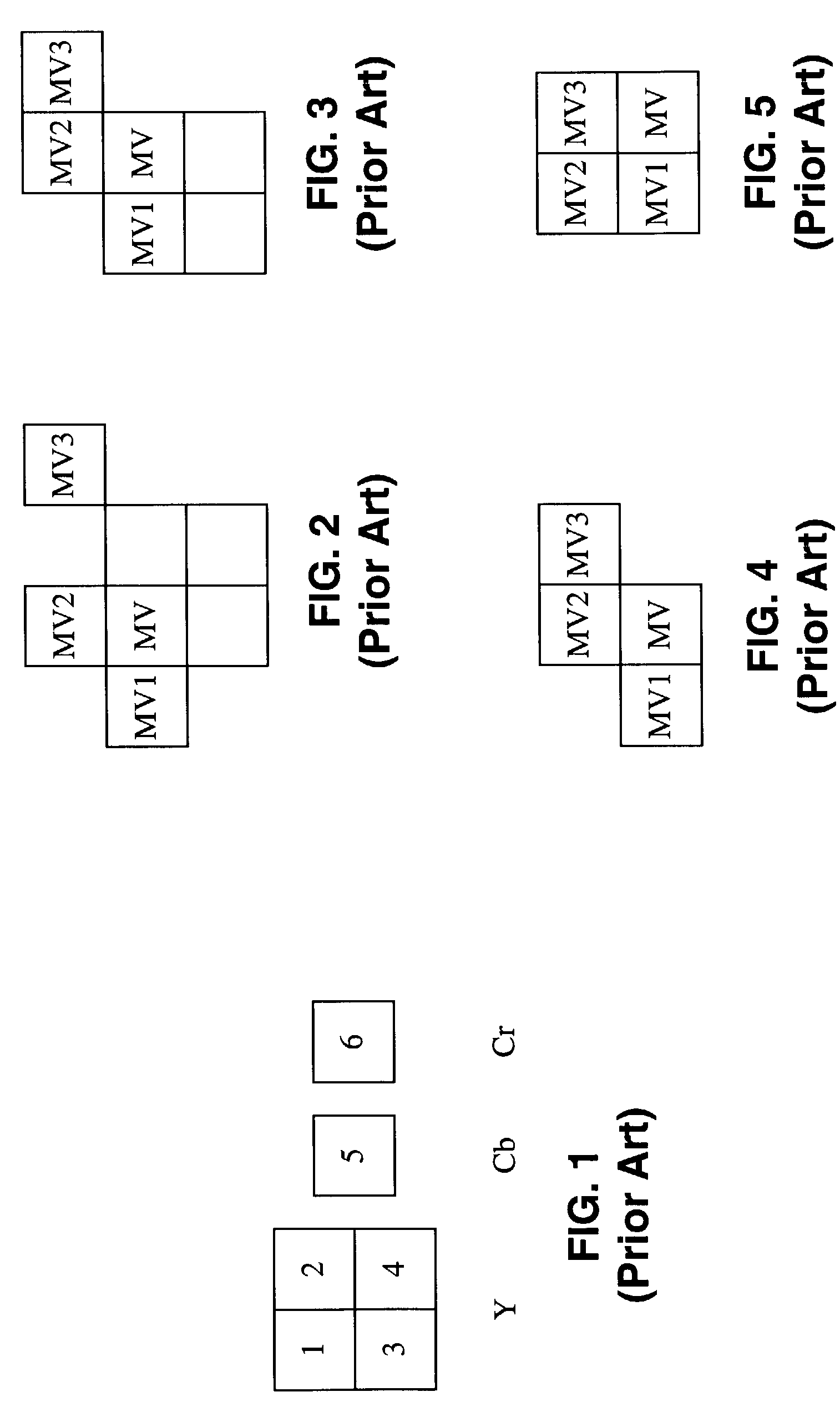
The conventional process by which the motion vectors are obtained is complicated by the fact that every condition described in the previous section must be evaluated.

Method used


Image

  • Fast motion vector prediction method
  • Fast motion vector prediction method
  • Fast motion vector prediction method

Examples


Embodiment Construction

[0035]Referring more specifically to the drawings, for illustrative purposes the present invention is embodied in the apparatus generally shown in FIG. 6 through FIG. 10. It will be appreciated that the apparatus may vary as to configuration and as to details of the parts, and that the method may vary as to the specific steps and sequence, without departing from the basic concepts as disclosed herein.

[0036]Location information within a macroblock is first categorized into states in response to horizontal and vertical components. The vertical direction is preferably classified into two cases (states), wherein the current macroblock is categorized as either being located on the upper-edge (Upper_Edge), or not being located on the upper-edge (Not_Upper_Edge). The horizontal direction is preferably classified into three cases (states), wherein the current macroblock is either located on the left-edge (Left_Edge), on the right-edge (Right_Edge), or not on an edge (Not_Edge). It should be...


PUM


Abstract

A method of rapidly generating motion vector predictions based on vertical and horizontal position categorization of macroblocks within a video object plane (VOP) for use within a video decoder or encoder. By way of example, the location of the subject macroblock is categorized vertically as either Upper_Edge or Not_Upper_Edge, and horizontally as either Left_Edge, Right_Edge, or Not_Edge. The position categories are utilized in conjunction with selected block number (Block1 through Block4) within the luminance macroblock within a decision-tree which generates three predictors MV1, MV2, and MV3. The prediction rules may be implemented within hardware, software, or combinations thereof, within both video encoders and decoders, such as according to the MPEG-4, H.263, or similar standards.

Description

CROSS-REFERENCE TO RELATED APPLICATIONS[0001]Not ApplicableSTATEMENT REGARDING FEDERALLY SPONSORED RESEARCH OR DEVELOPMENT[0002]Not ApplicableREFERENCE TO A COMPUTER PROGRAM APPENDIX[0003]Not ApplicableNOTICE OF MATERIAL SUBJECT TO COPYRIGHT PROTECTION[0004]A portion of the material in this patent document is subject to copyright protection under the copyright laws of the United States and of other countries. The owner of the copyright rights has no objection to the facsimile reproduction by anyone of the patent document or the patent disclosure, as it appears in the public files or records of the United States Patent and Trademark Office, but otherwise reserves all copyright rights whatsoever. The copyright owner does not hereby waive any of its rights to have this patent document maintained in secrecy, including without limitation its rights pursuant to 37 C.F.R. § 1.14.BACKGROUND OF THE INVENTION[0005]1. Field of the Invention[0006]This invention pertains generally to video proce...

Claims


Application Information

Patent Timeline
IPC IPC(8): H04N7/12G06T9/00H04N5/14H04N7/26
CPCH04N19/56H04N5/145
Inventor YOUN, JEONGNAM
Owner SONY CORP
Learn More