
Solar air conditioning system

a technology of solar energy and air conditioning system, which is applied in the field of solar energy air conditioning system, can solve the problems of inability to store foods and liquids requiring refrigeration, pollution to be released in the air, and inability to meet the needs of domestic cooling,

Inactive Publication Date: 2008-11-18
MUSCATELL RALPH
View PDF10 Cites 18 Cited by
  • Summary
  • Abstract
  • Description
  • Claims
  • Application Information

AI Technical Summary

Benefits of technology

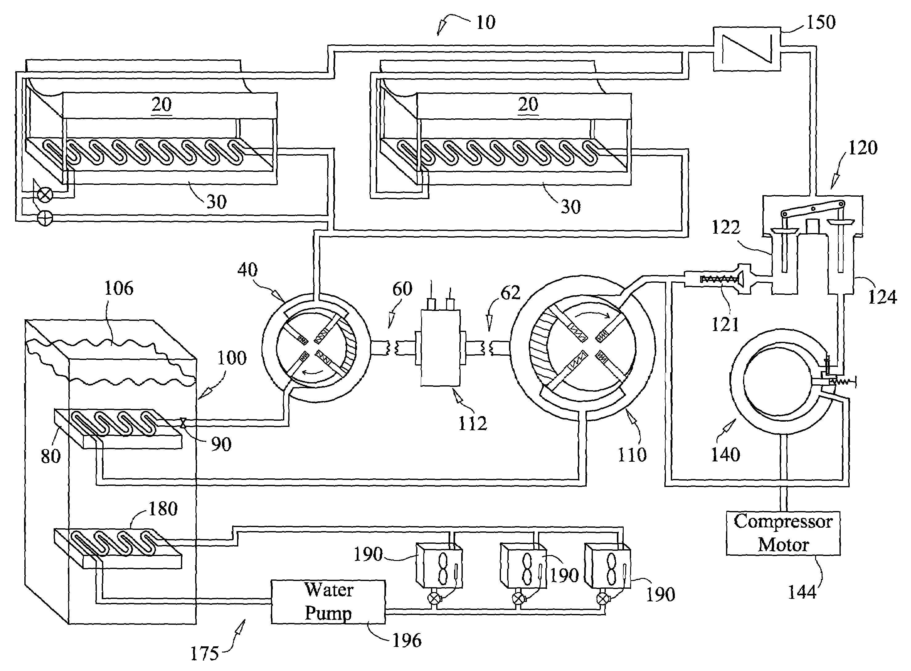
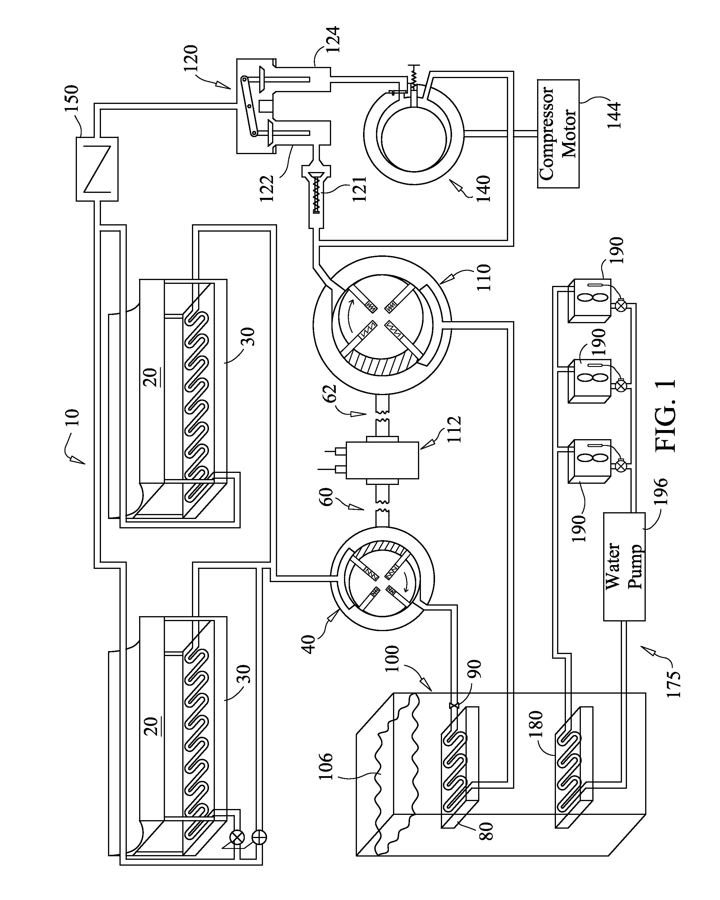
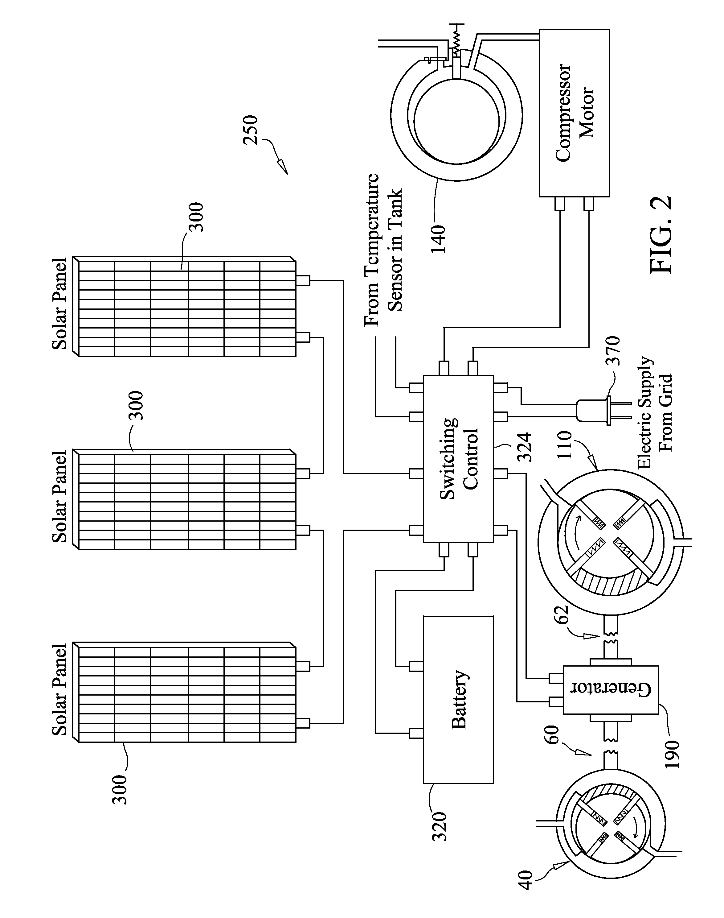
"The present invention is a solar air-conditioning system that uses concentrated solar energy and solar electric cells / battery to operate. The system has a heat exchanger that raises the temperature of a refrigerant, which is then expanded and cooled in an evaporator coil located in a water tank. The refrigerant system can also include a supplemental compressor and one-way direction valves to ensure proper gas direction. The system can also be used for large area coolers or refrigerators and can provide refrigeration where there is no electricity available. The technical effects of the invention include efficient use of solar energy, reduced reliance on electricity, and improved refrigeration in areas where it is needed."

Problems solved by technology

Additionally, the manufacture of energy at a power plant causes pollution to be released in the air.
Furthermore, electricity availability in undeveloped countries, as well as remote locations in developed countries, may be scarce, on limited basis or often non-existent.
As a result, these locations are unable to store foods and liquids requiring refrigeration due to the lack of electricity.
For undeveloped countries the lack of electricity is a factor in the poverty, hunger and lack of nourishment for its citizens.

Method used


Image

  • Solar air conditioning system
  • Solar air conditioning system
  • Solar air conditioning system

Examples


Embodiment Construction

[0023]As seen best in FIG. 1 a solar air-conditioning system is illustrated and generally referenced as system 10. System 10 includes one or more solar concentrators 20 and preferably a plurality of concentrators 20 preferably arranged in a parallel configuration or communication with each other. Concentrator(s) 20 capture energy from the sun raising the temperature and pressure of the refrigerant within the pipe, tubing, plumbing, conduits, hoses, etc. (all collectively referred to as “pipe” or “piping”) at the focal point. Though not considered limiting, the refrigerant can be Freon or ammonia gas. All of the pipe, valves, components, etc. of the present invention are preferably connected to each other through conventional connectors, fasteners, etc.

[0024]The refrigerant within the pipe proceeds or otherwise travels to the one or more heat dissipaters, commonly known as condensers 30, which can be large area condensers. The number of condensers 30 can correspond to the number of c...


PUM


Abstract

A solar air-conditioning system that is preferably designed to operate with concentrated solar heat and uses a circulating refrigerant in a cycle of compression and expansion. Solar concentrators raise the temperature and pressure of the refrigerant. The raised temperature is dissipated to the atmosphere and the refrigerant proceeds to the evaporator coil, which is located within a water tank containing at least 1000 gallons of an anti-freeze water solution. As the water is the storage medium, heat can be added to or extracted from the storage medium by the evaporator coil. A radiator pickup coil is also located within the water tank and is part of a separate chilled water system which can circulate its own water supply through other radiators located throughout a dwelling. Additionally, one or more bypass valve(s) within the refrigerant system allow switching to solar heating.

Description

[0001]This application claims the benefit of and priority to U.S. Application Ser. No. 60 / 853,531, filed Oct. 23, 2006, which is incorporated by reference in its entirety.[0002]1. Field of the Invention[0003]The present invention relates generally to air conditioning systems and particularly to a solar air conditioning system.[0004]2. Background of the Invention[0005]High electricity bills from air conditioning and / or heating use for a dwelling are common and reoccurring. Additionally, the manufacture of energy at a power plant causes pollution to be released in the air. Furthermore, electricity availability in undeveloped countries, as well as remote locations in developed countries, may be scarce, on limited basis or often non-existent. As a result, these locations are unable to store foods and liquids requiring refrigeration due to the lack of electricity. For undeveloped countries the lack of electricity is a factor in the poverty, hunger and lack of nourishment for its citizens...

Claims


Application Information

Patent Timeline
Patent Type & Authority Patents(United States)
IPC IPC(8): F25B27/00F24S90/00
CPCF24F5/0046F24J2/42F25B27/005Y02B10/20Y02B10/24Y02E10/40Y02B10/40Y02A30/272F24S90/00
Inventor MUSCATELL, RALPH
Owner MUSCATELL RALPH
Learn More