Method for using a tiltable stabilizer to reduce vibration generated on the fuselage of a helicopter

a technology of a helicopter fuselage and a tiltable stabilizer, which is applied in the direction of propellers, rotocraft, position/direction control, etc., can solve the problems of increasing drag and turbulence, affecting the structure as a whole and the mechanical elements of the helicopter, and reducing the level of vibration, so as to reduce or even eliminate the vibration generated.

Inactive Publication Date: 2008-11-18
EUROCOPTER
View PDF25 Cites 17 Cited by
  • Summary
  • Abstract
  • Description
  • Claims
  • Application Information

AI Technical Summary

Benefits of technology

[0023]An object of the present invention is to remedy these drawbacks. The invention provides a method making it possible to reduce or even eliminate, in simple and effective manner, the vertical vibration generated on the structure of a helicopter by the air flow or slipstream passing through the main rotor for providing lift and propulsion to said helicopter, and / or by the air flow along the fuselage, said helicopter having a substantially horizontal stabilizer that is tiltable at least in part, a fuselage, a main rotor for providing lift and propulsion, and where appropriate a tail rotor having blades of variable pitch.
[0028]Thus, by generating said opposing force, it is possible in simple and effective manner to reduce said vertical vibration, the drawbacks of which are mentioned above.
[0029]It should also be observed that the method of the invention is that much more effective in that it enables the aerodynamic excitation effect to be cancelled at source, i.e. at the substantially horizontal stabilizer itself, because of the way its angle of incidence is controlled. Consequently, the resonant modes of the fuselage cannot be excited merely by interference from the pulsating and turbulent slipstream coming from the main rotor and from the air stream along the fuselage.
[0038]In addition, in order to minimize any additional vibration, it is possible to generate variation in the angle of incidence of at least a portion of a tail fin.
[0046]The present invention also provides a device for reducing or even eliminating the vibration generated on the structure of a helicopter by the air flow or slip-stream passing through the main rotor for providing said helicopter with propulsion and lift, and / or by the air stream over the fuselage, said helicopter including at least a substantially horizontal stabilizer that is tiltable at the rear of the fuselage, having an angle of incidence that is controlled by a control system.

Problems solved by technology

. . ) which have the effect of spoiling (increasing drag and turbulence) the air flow from the fuselage itself.
Even if the aerodynamic excitation is relatively small, it can lead to a level of vibration that is disagreeable in the cockpit and in the passenger cabin and that is harmful for the structure as a whole and for the mechanical elements of the helicopter.
The various kinds of vibration due to the first lateral and / or vertical bending mode of the structure of the helicopter, and possibly also to a resonant mode in twisting of the helicopter, all present numerous drawbacks, including the following:a reduction in crew and passenger comfort;material and equipment fatigue; andproblems associated with operating on-board equipment such as weapons systems when the helicopter is fitted therewith.
Nevertheless, it has been found that the solution according to those patents FR 2 737 181 and U.S. Pat. No. 5,816,533 presents a first drawback associated with the fact that the aerodynamic excitation leads to excitation of resonant modes of the fuselage structure, and the blades of the tail rotor are controlled in order to reduce the vibration that results therefrom at certain particular points of the helicopter.
Unfortunately, that action tends to shift the vibration nodes and anti-nodes along the structure, but without thereby eliminating excitation of the resonant modes of said structure.
A second drawback of the system described in those patents lies in an increase in the level of noise that is generated because of the variations in the characteristic parameters (speed, pressure, .
These effects are harmful for the environment and raise severe problems in terms of regulations.
It should also be observed, by way of example, that another drawback due to changing the angle of incidence of the blades of the tail rotor for opposing the above-mentioned vibration lies in said variations in the angle of incidence of the blades of said rotor generally generating alternating forces and moments which reduce the lifetime of the assembly of parts constituting the rotor and the means for driving it in rotation.

Method used


Image

  • Method for using a tiltable stabilizer to reduce vibration generated on the fuselage of a helicopter
  • Method for using a tiltable stabilizer to reduce vibration generated on the fuselage of a helicopter
  • Method for using a tiltable stabilizer to reduce vibration generated on the fuselage of a helicopter

Examples


Embodiment Construction

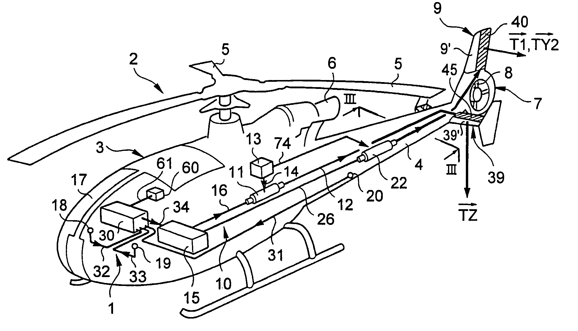
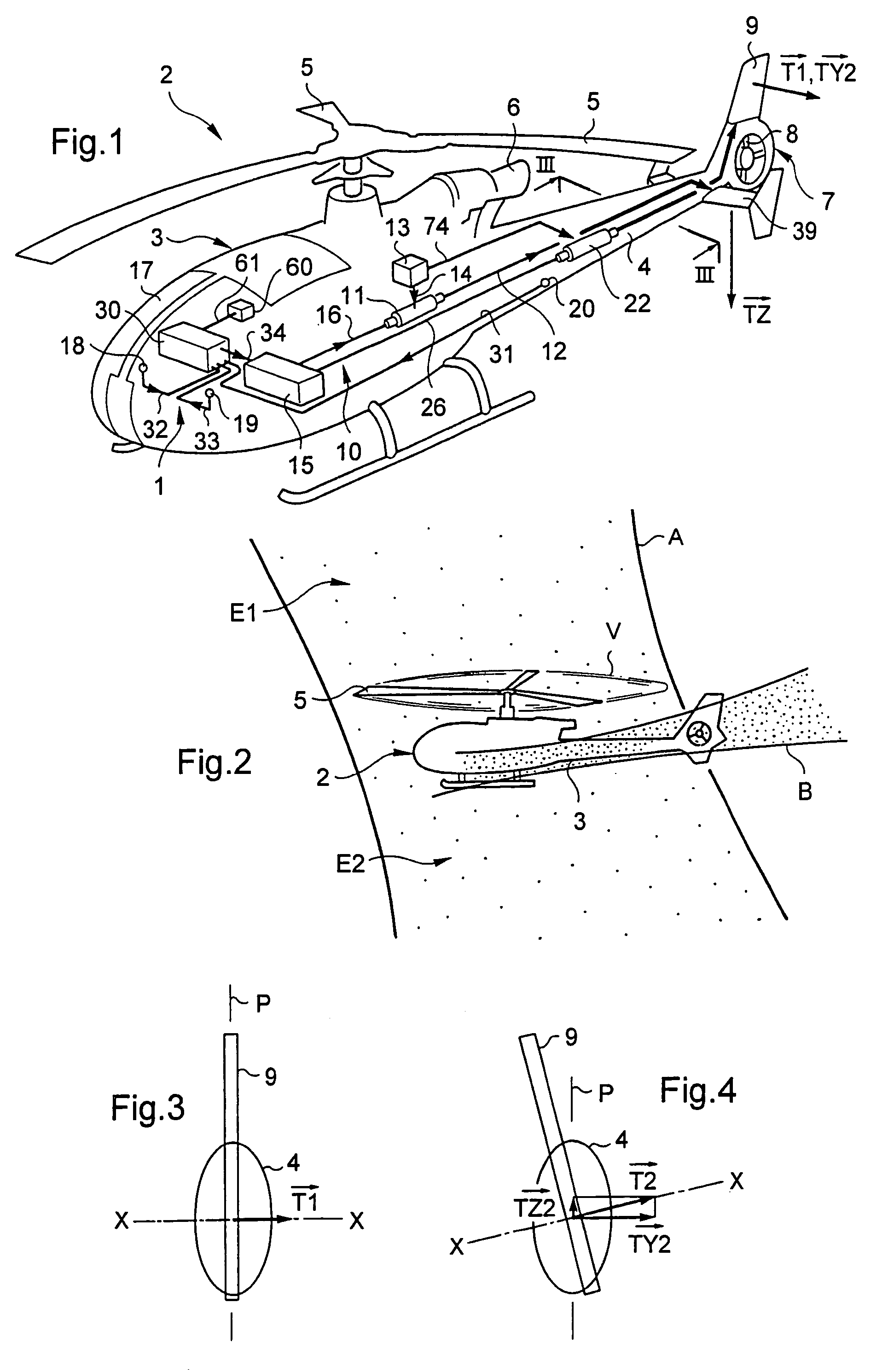
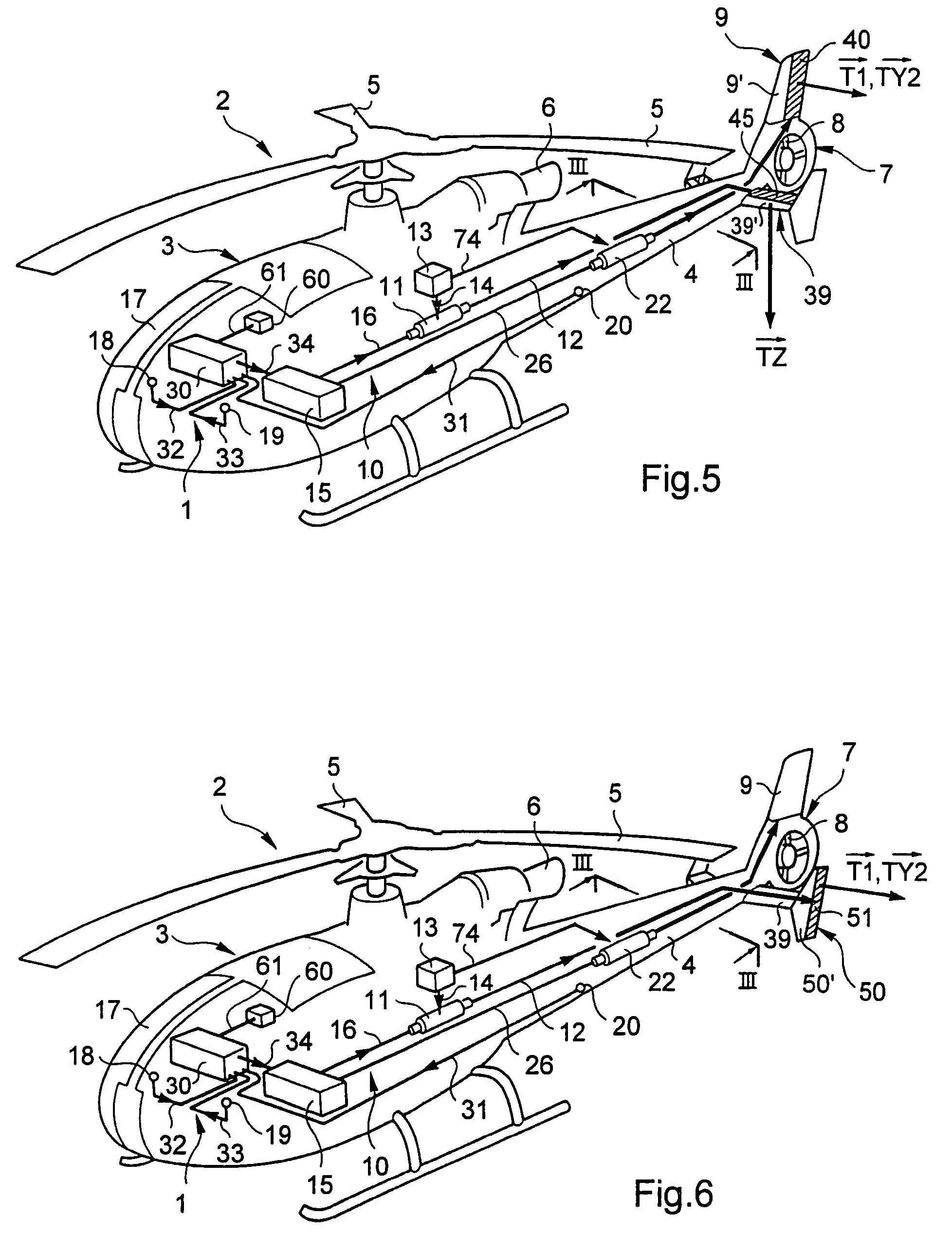
[0069]The device 1 of the invention and shown diagrammatically in FIG. 1 is intended to reduce vibration of the kind known as “tail shake”, which vibration occurs in the structure of a helicopter 2, as described below.

[0070]As can be seen in FIG. 1, said helicopter 2 comprises:[0071]a fuselage 3 extended rearwards by a tail boom 4;[0072]a main rotor 5 for providing lift and propulsion that is driven by means of drive delivered by an engine 6;[0073]a tail rotor 7 provided in known manner with blades 8 serving to compensate the yaw torque of said main rotor 5; and[0074]a substantially horizontal stabilizer 39.

[0075]Said substantially horizontal stabilizer 39 used for providing said helicopter 2 with stability in pitch can be tilted to vary its angle of incidence by means of a control system 10 which comprises:[0076]an actuator 11 or the like (connected to a connection 12 represented diagrammatically to said substantially horizontal stabilizer 39) and powered from a power source 13 via...


PUM


Abstract

A method and a device allow for reducing the vibration generated on the structure 17 of a helicopter 2 by the air flow through the main rotor 5 and by the air flow along the fuselage 3. The device 1 includes: at least one sensor 18, 19, 20 measuring the vibration generated on the structure 17; and computer element 30 responsive to the measurements to determine a variation in angle of incidence for a stabilizer 39 of the helicopter 2 that is suitable for generating a vertical opposing force {right arrow over (TZ)} for opposing the vertical vibration, with the variation in angle of incidence as determined in this way being transmitted to a system 10 for controlling the angle of incidence of the stabilizer 39.

Description

[0001]The present invention relates to a method and to a device for reducing the vibration generated on the structure of a helicopter both by the flow of air coming from the main rotor which serves to provide lift and propulsion to the helicopter and by the flow of air along its fuselage.BACKGROUND OF THE INVENTION[0002]It is known that when the main rotor turns, it sucks in air from upstream and blows it out downstream like a propeller, thereby allowing the helicopter to fly up and down. When flying forwards, the rotor acts both as a propeller and as a wing. As a propeller it accelerates the mass of air that passes through it so as to create a moving slipstream, with the pressure and the speed of the air varying along said slipstream. Acting as a wing, the rotor causes the slipstream to be deflected.[0003]The stream of air downstream from the main rotor, commonly referred to as the “slipstream”, is disturbed in part by the main elements for rotating the main rotor and by certain fa...

Claims


Application Information

Patent Timeline
Patent Type & Authority Patents(United States)
IPC IPC(8): G05D1/00B64C11/00B64C13/00B64C27/78B64C27/00
CPCB64C27/001
Inventor EGLIN, PAUL
Owner EUROCOPTER
Why Eureka
Try Eureka