
Vertical complementary fractal antenna

antenna technology, applied in the field of antennas, can solve the problem of limited ground radiation of antennas with a vertical complementary fractal structur

Inactive Publication Date: 2008-11-18
IND TECH RES INST
View PDF5 Cites 15 Cited by
  • Summary
  • Abstract
  • Description
  • Claims
  • Application Information

AI Technical Summary

Benefits of technology

The invention provides a vertical complementary fractal antenna that solves problems of previous antennas by having a fractal structure at both the upper and lower levels, with a ground connection plane in between. This increases ground radiation and reduces the overall size of the antenna while improving isolation from the circuit connected to it. The technical effects of this design include increased ground radiation, reduced size, and improved isolation.

Problems solved by technology

Previously, since antennas were simple in structure, the ground radiation of antennas with a vertical complementary fractal structure was limited.

Method used


Image

  • Vertical complementary fractal antenna
  • Vertical complementary fractal antenna
  • Vertical complementary fractal antenna

Examples


Embodiment Construction

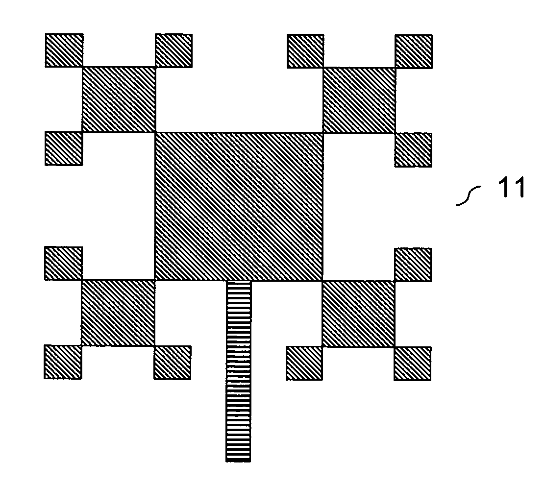
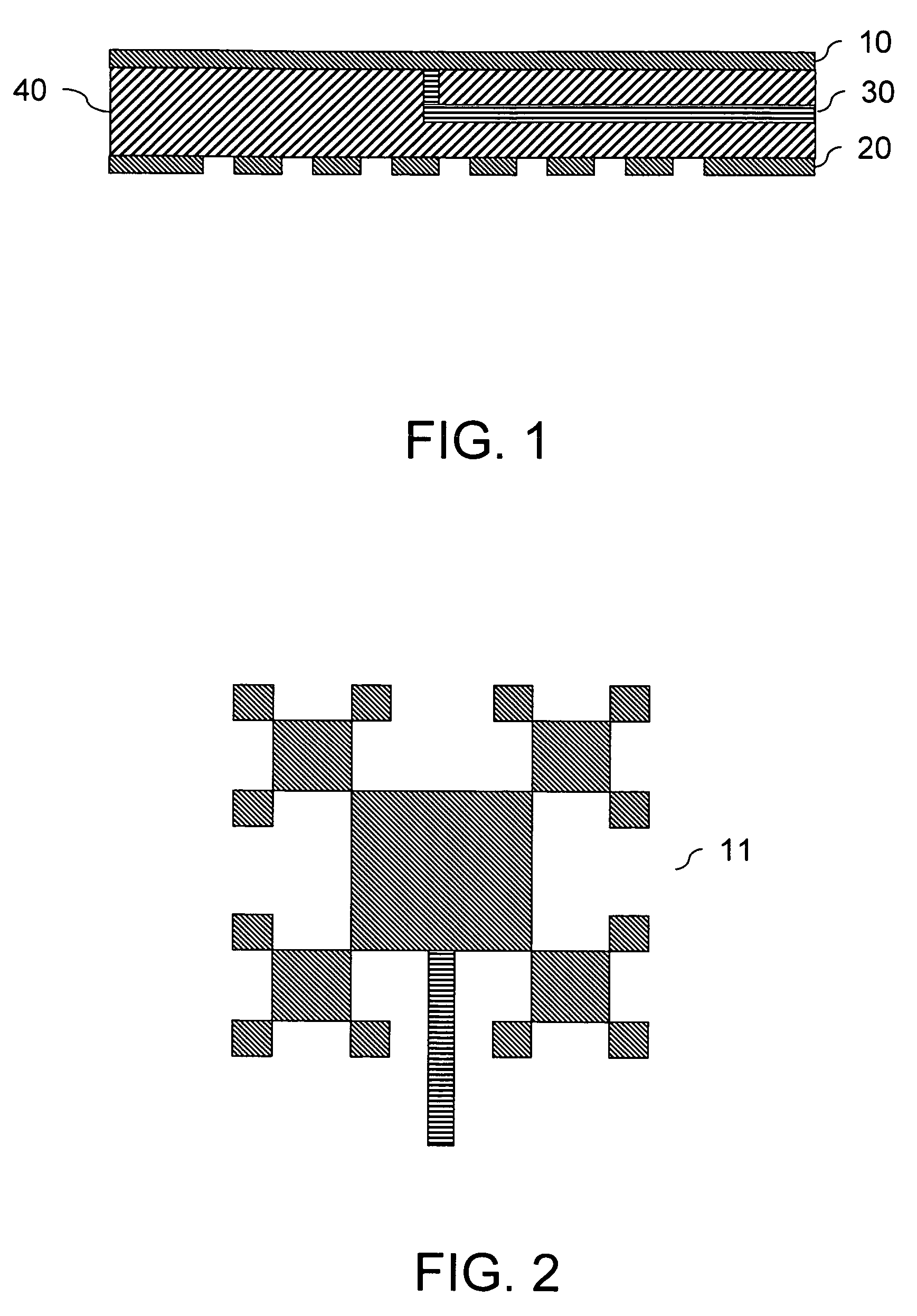
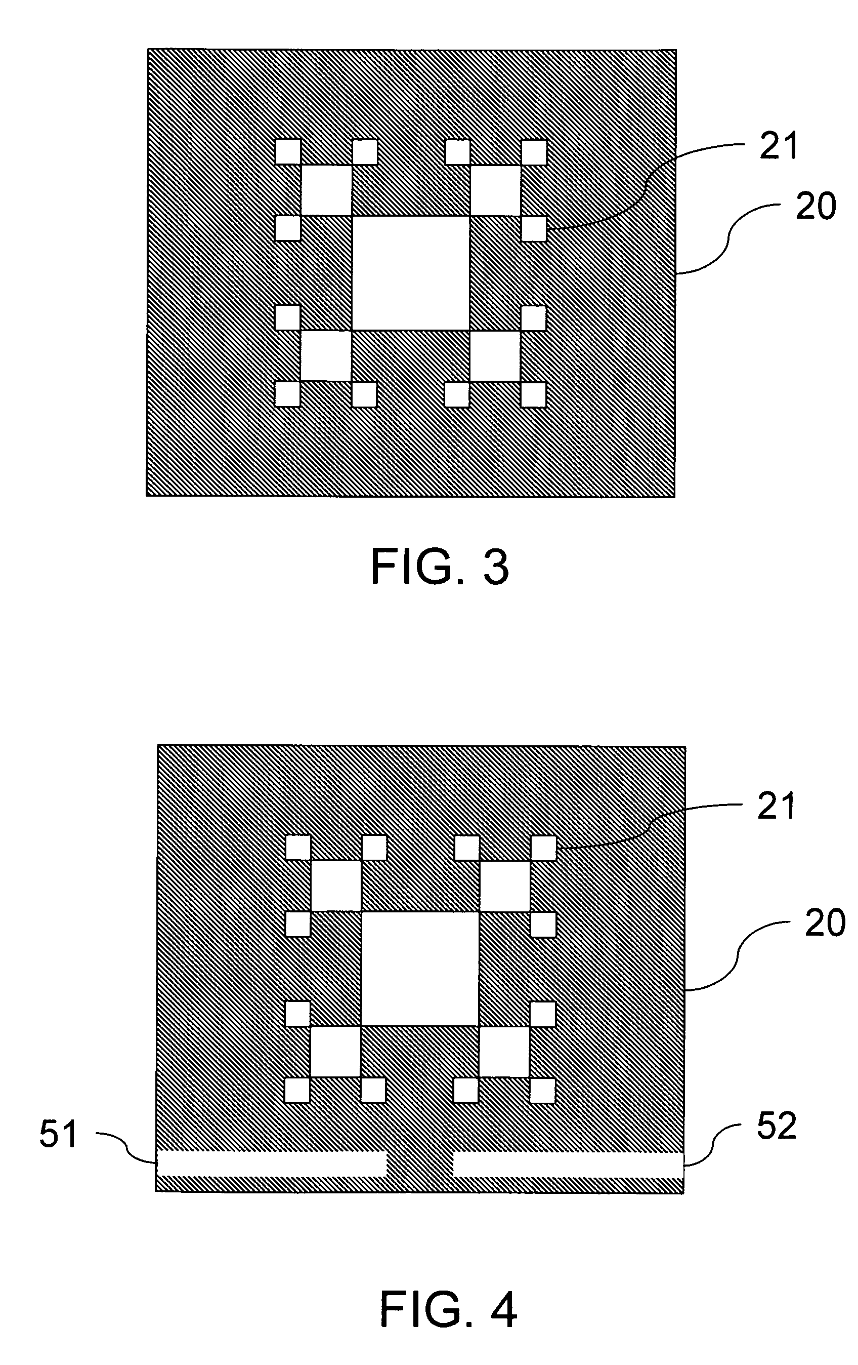
[0028]Reference will now be made in greater detail to a preferred embodiment of the invention, an example of which is illustrated in the accompanying drawings. Wherever possible, the same reference numerals are used throughout the drawings and the description to refer to the same or like parts. Reference in the specification to “one embodiment” or “an embodiment” means that a particular feature, structure, or characteristic described in connection with the embodiment is included in at least one embodiment of the invention. The appearances of the phrase “in one embodiment” in various places in the specification are not necessarily all referring to the same embodiment.

[0029]Referring to FIG. 1, a vertical complementary fractal antenna according to an exemplary embodiment of the invention includes a signal layer 10 and a ground layer 20. The signal layer 10 is connected to a signal source through a wire. Between the signal layer 10 and the ground layer 20 there is a medium, which is an...


PUM


Abstract

A vertical complementary fractal antenna is provided, which includes a first fractal structure and a second fractal structure. The first fractal structure is defined as a superposition over at least one iteration of a motif, while the second fractal structure has a pattern complementary to that of the first fractal structure. Thus, the antenna may effectively increase bandwidth.

Description

[0001]This application claims the benefit of Taiwan Patent Application No. 94117602, filed on May 27, 2005, which is hereby incorporated by reference for all purposes as if fully set forth herein.BACKGROUND OF THE INVENTION[0002]1. Field of Invention[0003]The invention relates to an antenna, and more specifically to an antenna with a vertical complementary fractal structure.[0004]2. Related Art[0005]With the rapid development of wireless communication and semiconductor technology, wireless communication has become an indispensable part of life. A wireless communication system is comprised of a transmitter / receiver and antennas, wherein the antennas are used to convert electrical energy into electromagnetic energy or vice versa. This is one of most important components in communication systems. Given the demand for the miniaturization and multi-band capability of electronic devices, the current trend of antenna design is towards miniaturization, structural simplification, and multi-b...

Claims


Application Information

Patent Timeline
Patent Type & Authority Patents(United States)
IPC IPC(8): H01Q1/38
CPCH01Q1/36
Inventor JOW, UEI-MING
Owner IND TECH RES INST
Learn More