Direct conversion receiving apparatus and celluar phone

a receiving apparatus and a technology for converting, applied in the direction of gain control, digital transmission, transmission, etc., can solve the problems of direct conversion system defects, ber deterioration, and the variation of transitional dc offset when the gain of a gain control amplifier is switched cannot be suppressed

Inactive Publication Date: 2008-11-18
PANASONIC CORP
View PDF3 Cites 10 Cited by
  • Summary
  • Abstract
  • Description
  • Claims
  • Application Information

AI Technical Summary

Benefits of technology

[0026]The present invention has been made taking the foregoing problems into consideration and an object of the present invention is to provide a direct conversion receiving apparatus capable of suppressing the transitional DC offset variation in the output of a high pass filter generated when switching the gain of a gain control amplifier as much as possible while suprressing the deterioration of a receiving signal during the normal operation by making the cutoff frequency of the high pass filter lower as much as possible, and a cellular phone using the same.

Problems solved by technology

However, the direct conversion system has defects, and one of them relates to a DC (direct current) offset variation.
However, only by inserting the high pass filter, a static DC offset variation can be suppressed, however, a transitional DC offset variation when the gain of a gain control amplifier is switched cannot be suppressed.
Since this period is very long, the BER is deteriorated.

Method used


Image

  • Direct conversion receiving apparatus and celluar phone
  • Direct conversion receiving apparatus and celluar phone
  • Direct conversion receiving apparatus and celluar phone

Examples


first embodiment

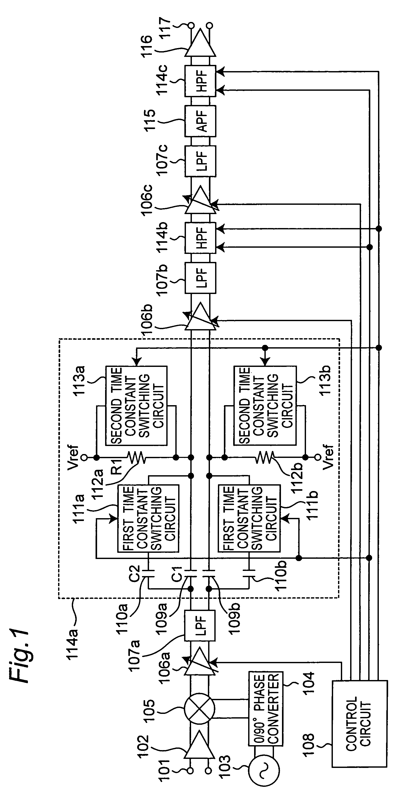
[0072]With reference to FIGS. 1 to 3, a direct conversion receiving apparatus of a first embodiment according to the present invention will be described below. FIG. 1 is a block diagram showing the structure of a direct conversion receiving apparatus according to the first embodiment of the present invention.

[0073]The direct conversion receiving apparatus according to the first embodiment of the present invention is configured by coupling in serial three stages each including of a gain control amplifier (GCA) 106a, 106b, or 106c; a low pass filter (LPF) 107a, 107b, or 107c; and a high pass filter (HPF) 114a, 114b, or 114c, respectively. The GCA 106b and 106c are the same structures as the GCA 106a. The LPF 107b and 108c are the same structures as the LPF 107a.

[0074]In FIG. 1 of the first embodiment, the same parts as the conventional example of FIG. 7 are provided with the same reference numerals. The direct conversion receiving apparatus according to the first embodiment of the pr...

second embodiment

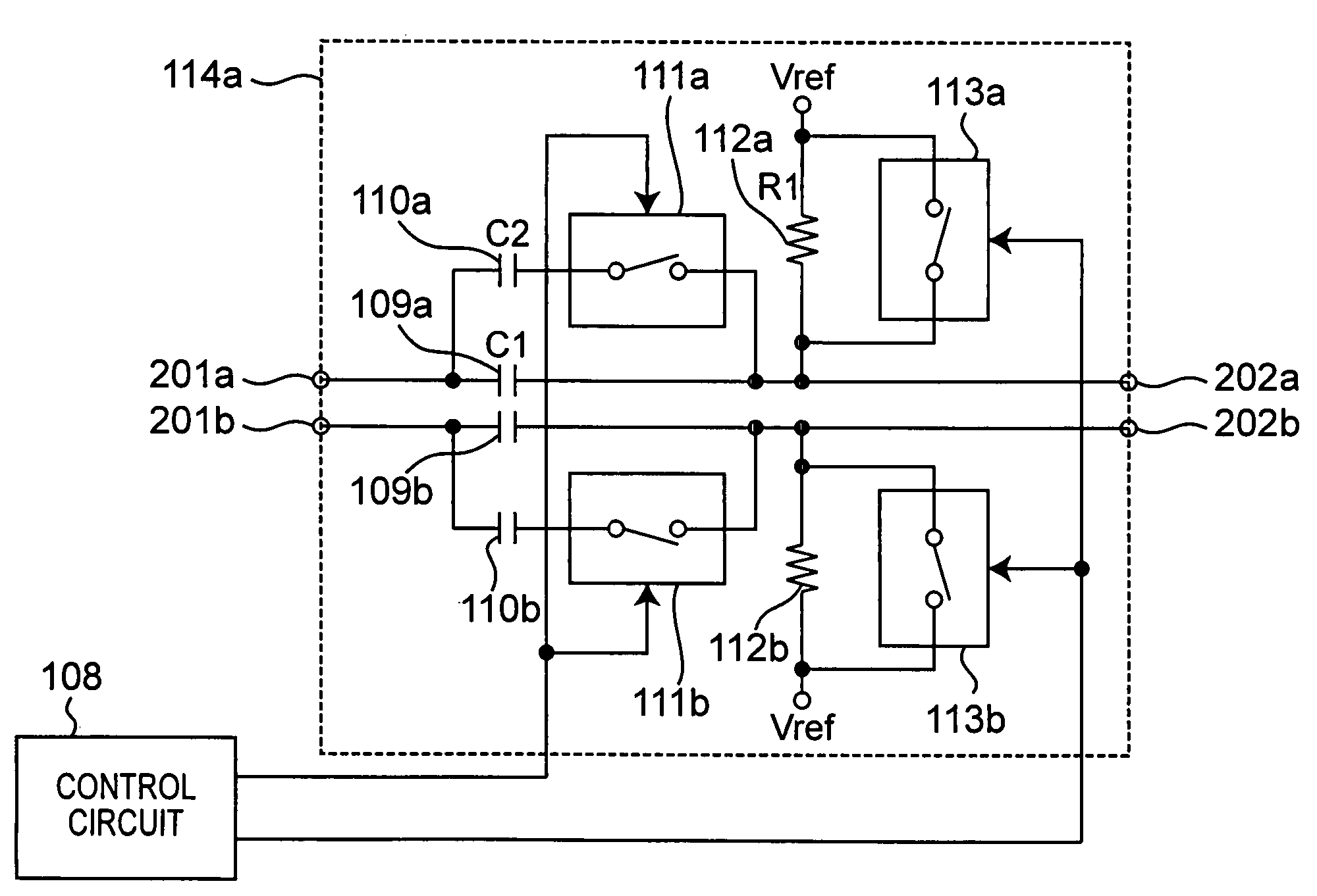
[0110]With reference to FIGS. 1, 3, and 4, the direct conversion receiving apparatus according to the second embodiment will be described below. The direct conversion receiving apparatus according to the second embodiment is different from the apparatus according to the first embodiment in the inner structures of the high pass filter (HPF) 114a, 114b, and 114c. With respect to other structures, the direct conversion receiving apparatus according to the second embodiment is the same as the apparatus according to the first embodiment. Since FIG. 1 and FIG. 3 are the same as the first embodiment, the detailed explanation thereof is herein omitted. Since the HPF 114a, 114b, and 114c have the same structures, the HPF 114a will be described below.

[0111]FIG. 4 is a block diagram showing the detailed structure of the high pass filter (HPF) 114a according to the second embodiment. The high pass filter (HPF) 114a according to the second embodiment has the first capacitors 109a, 109b for cutti...

third embodiment

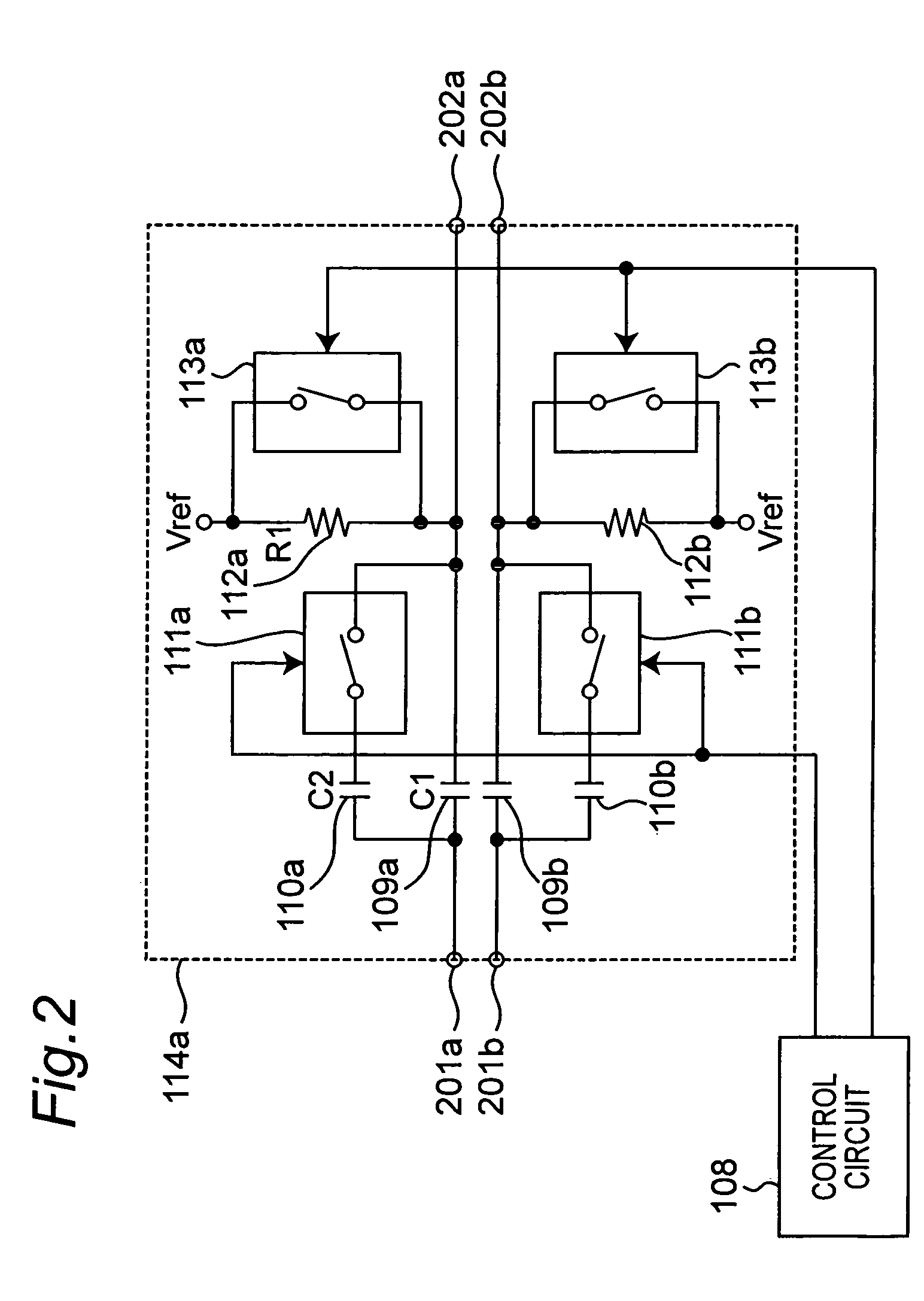
[0119]With reference to FIGS. 2, 3, and 5, the direct conversion receiving apparatus according to the third embodiment will be described below. Since FIG. 2 and FIG. 3 have been described in the first embodiment, the detailed explanation is herein omitted. FIG. 5 is a block diagram showing the structure of the direct conversion receiving apparatus according to the third embodiment. The direct conversion receiving apparatus according to the third embodiment is different from that according to the first embodiment in that the direct conversion receiving apparatus according to the third embodiment has high pass filters (HPF) 119b and 119c in place of the high pass filters (HPF) 114b and 114c. The HPF 114a according to the third embodiment has the same structure as that of the HPF 114a according to the first embodiment (FIGS. 1 and 2). In place of this, the HPF 114a may have the same structure as that of the HPF 114a according to the second embodiment (FIG. 4). The HPF 119b and the HPF ...


PUM


Abstract

The direct conversion receiving apparatus has a gain control amplifier for variably amplifying a base band signal based on a gain switching control signal. A high pass filter has a first circuit including capacitors connected in parallel that are inserted in a path connecting an input terminal to an output terminal and switching effective total capacitance of the capacitors based on a first time constant switching control signal, and a second circuit including a resistor for providing a predetermined direct current voltage to the output terminal and switching the effective resistance value of the resistor based on a second time constant switching control signal. A control circuit outputs the gain switching control signal, and the first and second time constant switching control signals according to the change of the gain control of said gain control amplifier.

Description

BACKGROUND OF THE INVENTION[0001]1. Field of the Invention[0002]The present invention generally relates to a direct conversion receiving apparatus and a cellular phone, and particurally, to a wireless direct conversion receiving apparatus provided with a structure for supressing transitional DC offset variation when the gain of a gain control amplifier is switched, and a cellular phone using the same.[0003]2. Description of the Related Art[0004]In recent years, in a receiving apparatus for wireless communication such as a cellular phone, miniaturization and a low cost have been highly required. As a system capable of decreasing the number of parts, a direct conversion system has been known. The direct conversion system is a system to multiply a high frequency (RF) signal received by an antennal by a local oscillation signal (a local signal) of the substantially same frequency as the high frequency and directly take out a base band signal while omitting conversion into a middle frequ...

Claims


Application Information

Patent Timeline
Patent Type & Authority Patents(United States)
IPC IPC(8): H04B1/26
CPCH03G1/04H03G3/3052H03G3/3078H04B1/30
Inventor YONEDA, TAKUJIKURIMOTO, HIDEHIKOISHIDA, KAORU
Owner PANASONIC CORP
Why Eureka
Try Eureka