Deposition friction stir welding process and assembly

a friction stir welding and assembly technology, applied in the direction of welding devices, soldering devices, manufacturing tools, etc., can solve the problems of general thinning of material along the weld line, not always feasible nor cost effective, and current methods that are not entirely effective at eliminating the exit keyhole

Inactive Publication Date: 2008-11-25
GENERAL ELECTRIC CO
View PDF14 Cites 26 Cited by
  • Summary
  • Abstract
  • Description
  • Claims
  • Application Information

AI Technical Summary

Benefits of technology

[0008]In another embodiment, a process for depositing and contouring a surface of a work piece comprises frictionally heating a selected surface of the work piece at a temperature below a melting point of the work piece, wherein the selected surface softens; and containing the softened surface with a die to contour the surface and prevent flash material from being discharged during the frictional heating.
[0009]In yet another embodiment, a spot friction weld process comprises frictionally heating a spot on a work piece surface to a temperature effective to soften a region at and about the spot, wherein the temperature is below a melting point of the work piece surface; and containing the spot to prevent discharge of a flash material from the work piece surface.

Problems solved by technology

Providing a run-out region that can subsequently be removed can eliminate the exit keyhole, but this is not always feasible nor cost effective.
Current methods are not entirely effective at eliminating the exit keyhole effect.
Another one of the ongoing problems with current friction stir welding processes is that the welding process has a tendency to produce flash material and also results in a general thinning of material along the weld line.
This strength reduction must be mitigated by a thickness compensated design and this penalty can be significant in many situations especially for plate joining applications where additional thickness penalties must be made across the entire width of the plate.
Moreover, the production of flash material presents safety concerns for handling personnel and requires further post-processing.

Method used


Image

  • Deposition friction stir welding process and assembly
  • Deposition friction stir welding process and assembly
  • Deposition friction stir welding process and assembly

Examples


Embodiment Construction

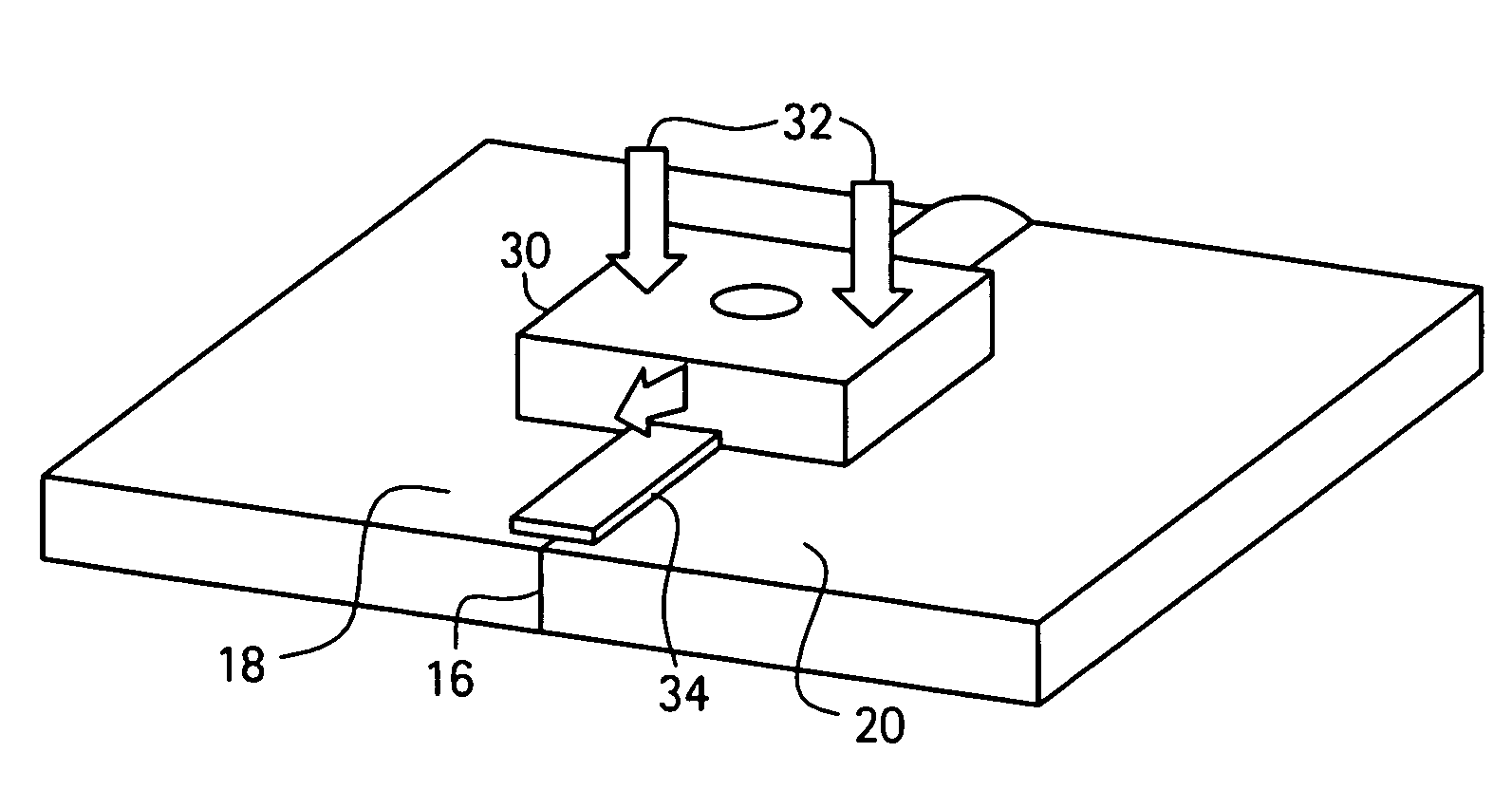
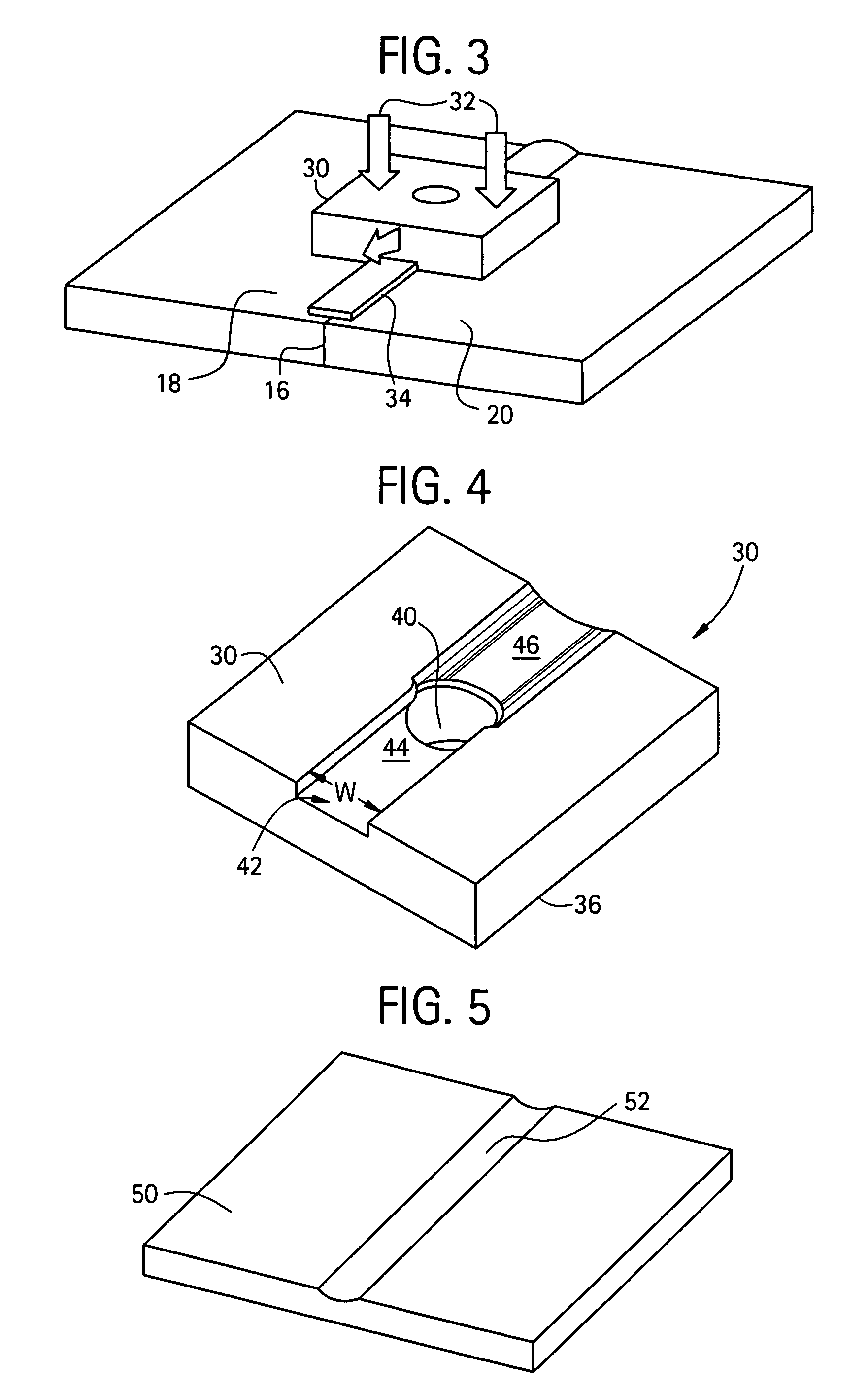
[0021]Applicant has discovered a process of friction stir welding that compensates for the production of flash and general thinning of material along the joint line during the solid-state joining process of two or more work pieces. The friction stir welding process in accordance with the present disclosure utilizes a so-called deposition friction stir welding process that generally includes depositing an additional solid-state material (also referred to herein as filler material) to the joint region along the joint line during the friction stir welding of two or more butted work pieces. As will be described in greater detail below, the additional solid-state material is introduced to the joint region in such a manner so as to contain the weld free surface as well as shape the resulting weld profile. As such, the resulting weld joint can be produced with a relatively thicker cross sectional thickness than prior art friction stir welding processes, thereby overcoming many of the above...


PUM

PropertyMeasurementUnit
temperatureaaaaaaaaaa
melting pointaaaaaaaaaa
thicknessaaaaaaaaaa

Abstract

A deposition friction stir weld process of joining work pieces includes placing a filler material on and about a joint line formed by butting a first work piece surface against a second work piece surface; and frictionally heating the filler material to soften the filler material and portions of the first and second work piece surfaces in thermal contact with the filler material and form a weld between the first and second work pieces, wherein frictionally heating is at a temperature below a melting point of the filler material and the first and second workpiece surfaces. Also disclosed herein are friction stir welding assemblies for providing the deposition friction stir weld as well as processes for depositing filler material and contouring a workpiece surface.

Description

BACKGROUND[0001]The present disclosure generally relates to friction stir welding and, more specifically, to processes of friction stir welding that include providing an additional solid-state source during the friction stir welding.[0002]Friction stir welding is a solid-state joining process that that provides material deformation similar to that of extrusion forging. Since the friction stir welding process occurs at a temperature below the melting point of the work piece material, solidification-related defects that are common in fusion type welds, for example, are substantially eliminated, and friction stir welding generally provides relatively higher joint strengths. Additionally, the lower heat input used in the friction stir welding process as opposed to other welding processes results in less residual stress, less distortion, and less impact to the final metallurgical properties of the work piece. Many joint designs are possible using friction stir welding including, but not ...

Claims


Application Information

Patent Timeline
Patent Type & Authority Patents(United States)
IPC IPC(8): B23K20/12B23K31/02B23K37/00
CPCB23K20/1245B23K20/1255B23K20/128B23K2201/18B23K2101/18
Inventor MIKA, DAVID PETER
Owner GENERAL ELECTRIC CO
Why Eureka
Try Eureka