Aerial refueling system

a technology of refueling system and airframe, which is applied in the direction of aircraft components, transportation and packaging, thin material handling, etc., can solve the problems of overfilling of the fuel tank of the receiving aircraft and subsequent discharge of fuel by the relief valv

Active Publication Date: 2008-12-02
THE BOEING CO
View PDF80 Cites 55 Cited by
  • Summary
  • Abstract
  • Description
  • Claims
  • Application Information

AI Technical Summary

Benefits of technology

[0009]The air refueling system of the present invention offers several advantages. A computer system automatically controls the selection and operation of any number of pumps during fuel transfer, eliminating the need to manually monitor fuel flow and pressure and manually adjust the number of operating pumps. Electrically operated valves are also provided which are automatically controlled by the computer system, for automatically isolating or opening one or more flow paths. The ability to manually control the loading of fuel or moving fuel between tanks using the pumps is also an advantageous feature of the air refueling system. Fuel can be directed to / from any tank individually or simultaneously. Reverse air refueling operation of the tanker aircraft can also be accomplished via manual control of valves and pumps while in receiver mode. Reverse air refueling through a boom of another aircraft can also be accomplished in receiver mode.

Problems solved by technology

Because of the use of manual monitoring and manual shut-off of fuel flow, operation of these refueling systems also can result in overfilling of the receiving aircraft fuel tanks and subsequent relief valve discharge of fuel.

Method used


Image

  • Aerial refueling system
  • Aerial refueling system
  • Aerial refueling system

Examples


Embodiment Construction

[0016]The following description of the preferred embodiments is merely exemplary in nature and is in no way intended to limit the invention, its application, or uses.

[0017]It is initially noted that an aerial refueling system (ARS) of the present invention can be installed or backfitted into a plurality of refueling or tanker aircraft designs, including but not limited to the Boeing 767, Boeing 757, KC-135 and / or KC-10 aircraft. For exemplary purposes only, the present application refers in general to installation in the Boeing 767, including structure and equipment common to that aircraft.

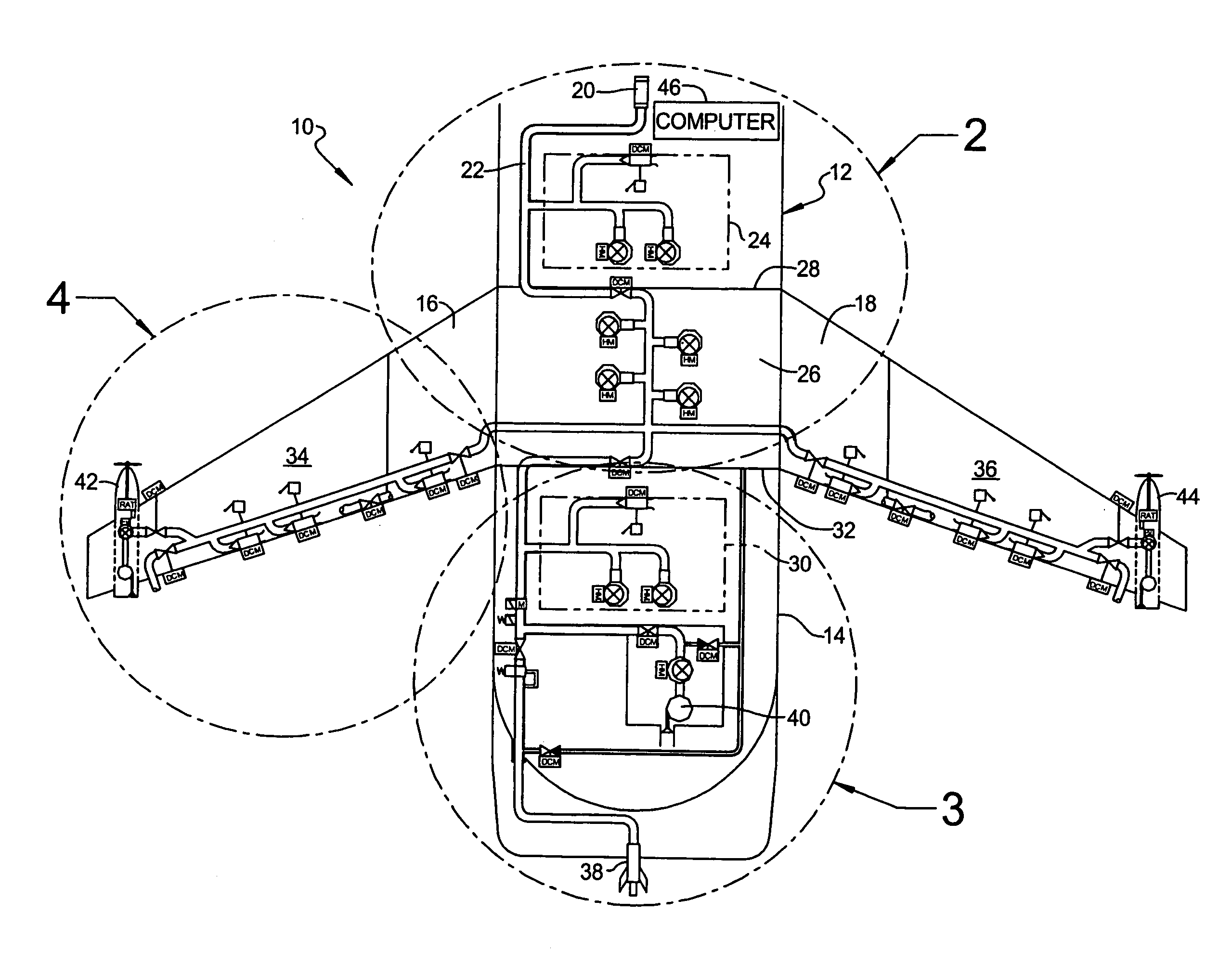
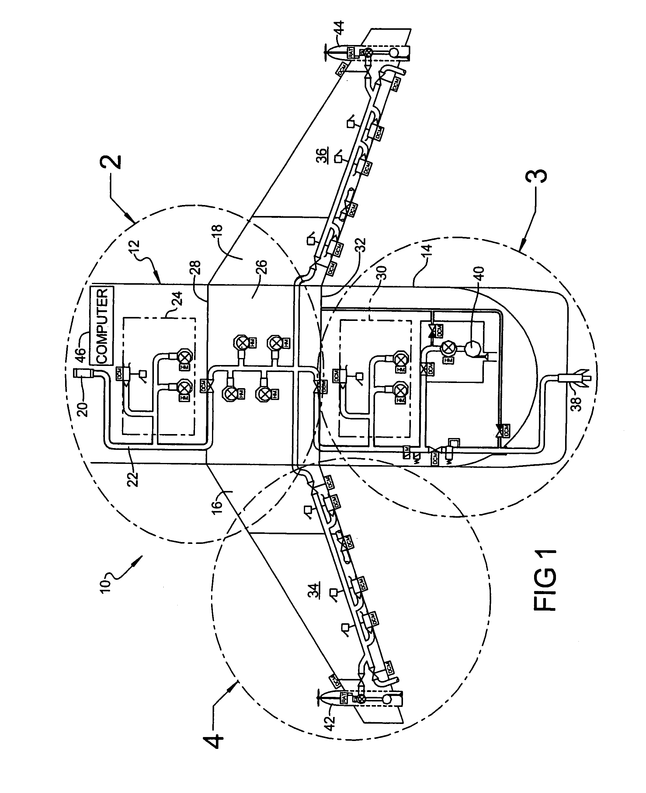
[0018]According to one preferred embodiment of the present invention and referring generally to FIG. 1, ARS 10 is mounted on a tanker aircraft 12 having a fuselage 14, a port wing 16 and a starboard wing 18. ARS 10 includes a receptacle 20 such as a universal aerial refueling receptacle slipway installation which can either receive or transfer fuel. Receptacle 20 is connected to a refueling manifo...


PUM


Abstract

An aircraft aerial refueling system includes a fuel tank positioned in at least an aircraft wing to store fuel. At least two fuel pumps operate to transfer the fuel from the tank to a remotely located refueling connection. At least one electrically controlled valve provides each of an open position permitting fuel flow and a closed position isolating fuel flow between the tank and the refueling connection. A computer system automatically varies operation of any quantity of the fuel pumps and controls the electrically controlled valve between the open and closed positions during fuel transfer to the refueling connection. double wall fuel pipe manifolds in manned spaces of the aircraft.

Description

CROSS-REFERENCE TO RELATED APPLICATIONS[0001]This application claims the benefit of U.S. Provisional Application No. 60 / 689,666, filed on Jun. 10, 2005. The present application is generally related to subject matter disclosed in co-filed applications: “Shrouded Body Flow Meter Assembly,” U.S. Provisional Application No. 60 / 689,677, filed on Jun. 10, 2005; “Shrouded Valve Apparatus And Related Methods,” U.S. Utility application Ser.No. 11 / 150,853, filed on Jun. 10, 2005; “Fittings With Redundant Seals For Aircraft Fuel Lines, Fuel Tanks, And Other Systems,” U.S. Utility application Ser. No. 11 / 301,131, filed on Dec. 12, 2005; “Systems And Methods For Reducing Surge Loads In Hose Assemblies, Including Aircraft Refueling Hose Assemblies,” U.S. Utility application Ser. No. 11 / 258,819, filed on Oct. 26, 2005; “Adjustable Fittings For Attaching Support Members To Fluid Conduits, Including Aircraft Fuel Conduits, And Associated Systems And Methods,” U.S. Utility application Ser. No. 11 / 440...

Claims


Application Information

Patent Timeline
Patent Type & Authority Patents(United States)
IPC IPC(8): B64D39/00
CPCB64D39/00Y10T137/0318Y10T137/4857Y10T137/4673
Inventor CUTLER, THERON L.SHELLY, MARK A.
Owner THE BOEING CO
Why Eureka
Try Eureka