
Device and method for determining the properties of surfaces

a technology of surface properties and devices, applied in measurement devices, material analysis through optical means, instruments, etc., can solve problems such as substantially collimated ligh

Active Publication Date: 2008-12-02
BYK GARDNER
View PDF8 Cites 6 Cited by
  • Summary
  • Abstract
  • Description
  • Claims
  • Application Information

AI Technical Summary

Benefits of technology

[0010]Further, the device of the invention comprises at least one radiation detector means which captures at least a portion of the radiation reflected and / or diffused off the measurement surface and emits at least one measurement signal which is characteristic of the reflected and / or diffused radiation. The radiation detector means may also comprise a device suitable for detecting incident radiation dependent on its wavelength. For example, a monochromator may be provided or generally at least one dispersive component such as transmission or reflection gratings or the like. Preferably said angle, which is formed by a geometrical connecting axis from the radiation detector means to the geometrical center of the measurement surface and projection of said connecting axis onto the measurement surface, is variable wherein the distance between the radiation detector means and the measurement surface preferably remains substantially constant. The device of the invention is remarkable in that the space above the measurement surface possesses substantially radiation-absorbing properties wherein the radiation captured by and reflected and / or diffused off the radiation detector means is substantially only that radiation diffused and / or reflected off the surface to be examined. Otherwise possible multiple reflection or diffusion would considerably complicate any interpretation of the measurement signals determined by the radiation sensors for characterizing the surface. Besides it should also be prevented that light reflected or diffused off the measurement surface is reflected through the space above the measurement surface and in turn transmitted to the measurement surface as non-collimated light. However, corresponding embodiments which can eliminate the influence of such effects using calculation techniques of the provided processor means are likewise conceivable.
[0019]In a further advantageous embodiment of the device of the invention, the at least one first and at least one second radiation means are mounted in a housing above the measurement surface. In this way, for example an influence of radiated interference caused by daylight can be prevented.
[0037]This will be in particular advantageous when the measurement surface areas to be examined at specified times by different measurement means are physically separate so that if the measurement signals are to be correlated they can be stored temporarily and subsequently allocated to one another and to the matching location on the measurement surface.

Problems solved by technology

One drawback of these measuring devices is that they use substantially collimated light, i.e. directional parallel light beams for determining the reflection or diffusion characteristics of the object to be examined.
However, finished surfaces in particular may also show properties whose overall impression will only become apparent to a human observer on overcast days because then the light will impinge on the surface to be examined from a plurality of directions, being scattered by the clouds i.e. uncollimated or diffused, respectively.
Thus the problem is that the impression which the surface actually gives to a human observer results from the kind of illumination, i.e. whether the object is illuminated by collimated and / or uncollimated light or these types interact.

Method used


Image

  • Device and method for determining the properties of surfaces
  • Device and method for determining the properties of surfaces

Examples


Embodiment Construction

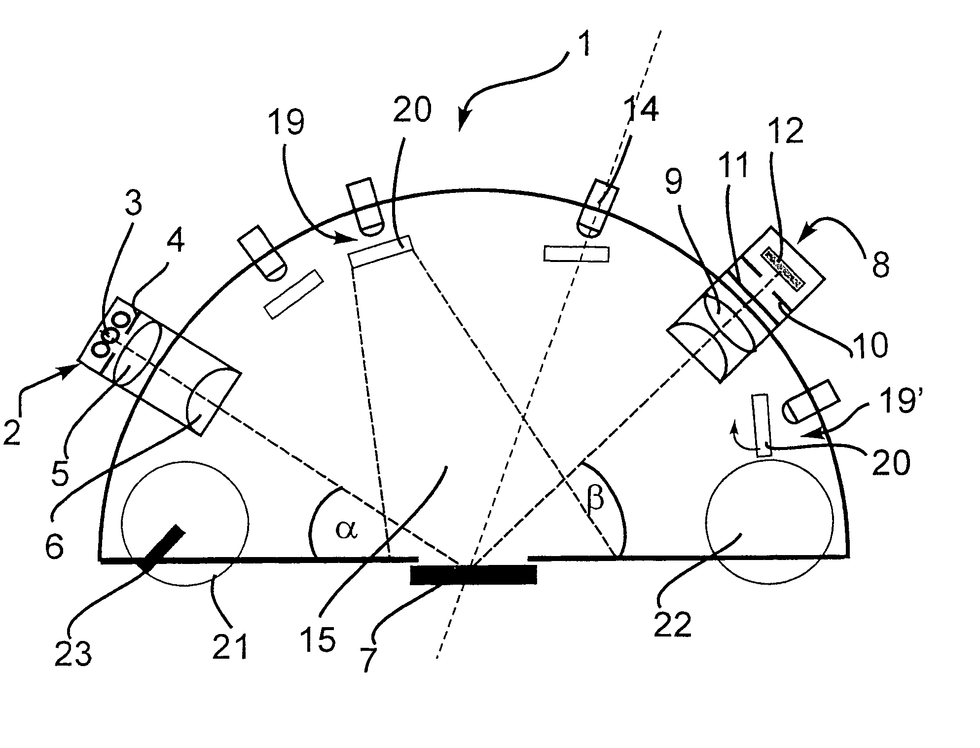
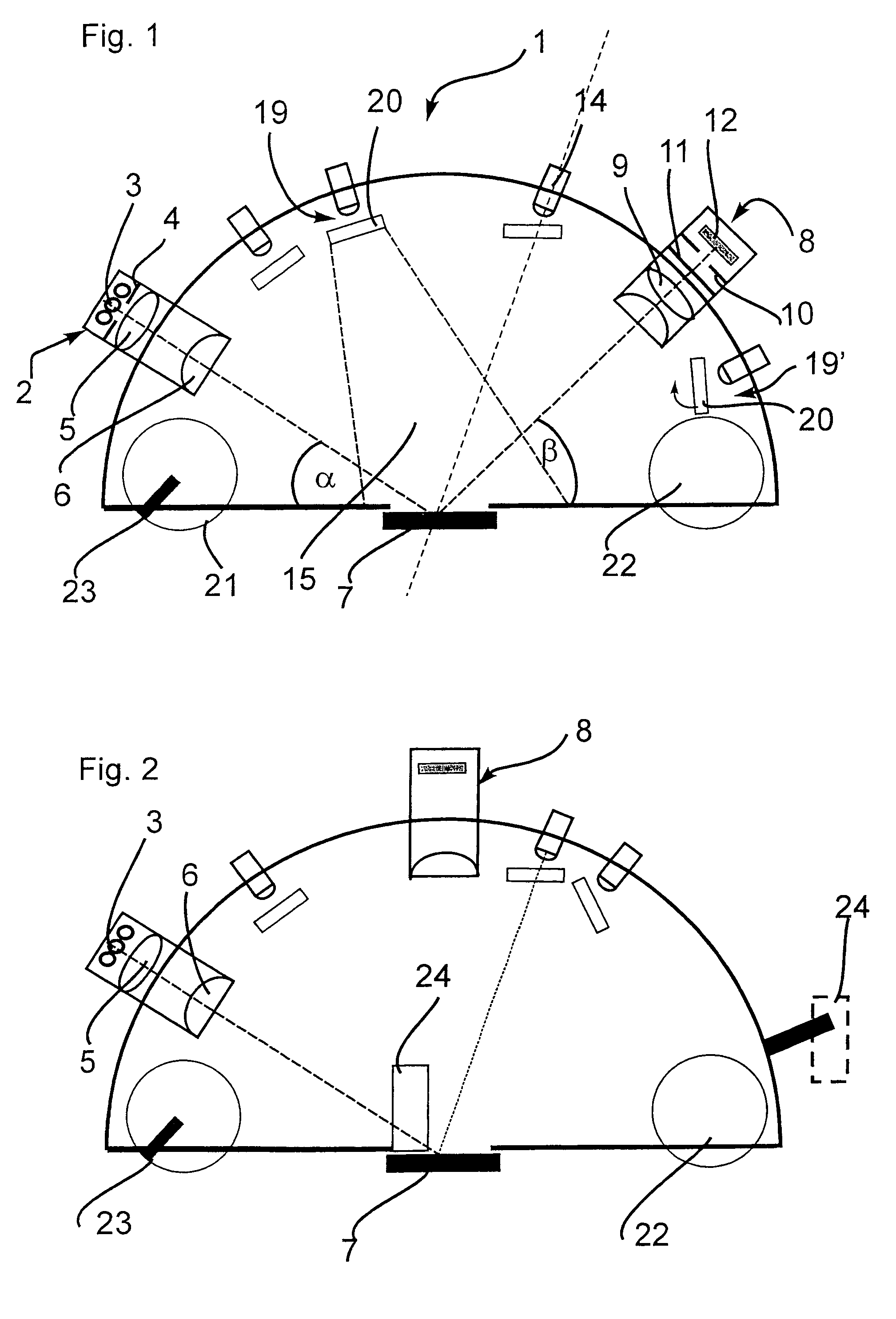
[0046]The device illustrated schematically in FIG. 1 for determining the properties of surfaces comprises a hemispherical housing 1 in which a first radiation means 2 is positioned at a specified angle a relative to a measurement surface 7.

[0047]The radiation in the present embodiment is light visible to the human eye. Corresponding to the device of the invention, utilizing radiation of other wavelengths such as infrared or UV radiation may, however, also be useful and advantageous.

[0048]The radiation means 2 includes—indicated schematically—three light sources 3, a diaphragm 4 and a lens means 5. The light emitting from one of the light sources 3 is limited in its aperture 6 by the diaphragm 4 and collimated by the lens means 5, i.e., it is substantially bundled in parallel and impinges on the measurement surface 7 to be examined through the aperture 6.

[0049]The measurement surface 7 reflects at least a portion of the light, causing it to enter into a radiation detector means 8 whi...


PUM


Abstract

The present invention relates to a device and a method for determining the properties of surfaces having at least one first radiation means for collimated irradiation of a measurement surface to be examined and at least one second radiation means for non-collimated irradiation of said measurement surface wherein the space above said measurement surface has substantially radiation-absorbing properties.The device of the invention further comprises at least one radiation detector means which captures at least a portion of the radiation reflected and / or diffused off the surface to be examined and emits at least one measurement signal which is characteristic of the reflected and / or diffused radiation.

Description

BACKGROUND OF THE INVENTION[0001]The present invention relates to a device and a method for determining the properties of surfaces.[0002]The quality of visible surfaces is a significant property of objects used in everyday life such as furnishings and consumer items such as cars and the like, thus decisively determining their overall impression on a human observer. An example therefor are high-gloss or metallic finishes of car bodies. The reproducible evaluation of the quality of surfaces in particular of said high-gloss finishes requires measuring instruments which capture precisely those physical quantities which decisively determine the overall impression on a human observer. Various methods and devices are known in the prior art for determining the visual properties and specifically the reflection characteristics of surfaces.[0003]One drawback of these measuring devices is that they use substantially collimated light, i.e. directional parallel light beams for determining the ref...

Claims


Application Information

Patent Timeline
IPC IPC(8): G01N21/00G01N21/01G01N21/57G01N21/84G01N21/95
CPCG01N21/57G01N21/8422G01N21/9515
Inventor SCHWARZ, PETER
Owner BYK GARDNER
Learn More