Low density, high rigidity disk drive suspension for high resonance frequency applications

Active Publication Date: 2008-12-02
MAGNECOMP
View PDF14 Cites 39 Cited by
  • Summary
  • Abstract
  • Description
  • Claims
  • Application Information

AI Technical Summary

Benefits of technology

[0017]In a further method aspect the invention provides a method of supporting a slider at a disk with a cantilevered component having at least three metal layers, including reducing the density of at least one of said three layers with interior voids, ra

Problems solved by technology

The presence of the polyimide means that there are different coefficients of thermal expansion (CTE) across the layers of the laminate which can cause distortions in these precision parts.
Also, the common practice of chemic

Method used


Image

  • Low density, high rigidity disk drive suspension for high resonance frequency applications
  • Low density, high rigidity disk drive suspension for high resonance frequency applications
  • Low density, high rigidity disk drive suspension for high resonance frequency applications

Examples


first embodiment

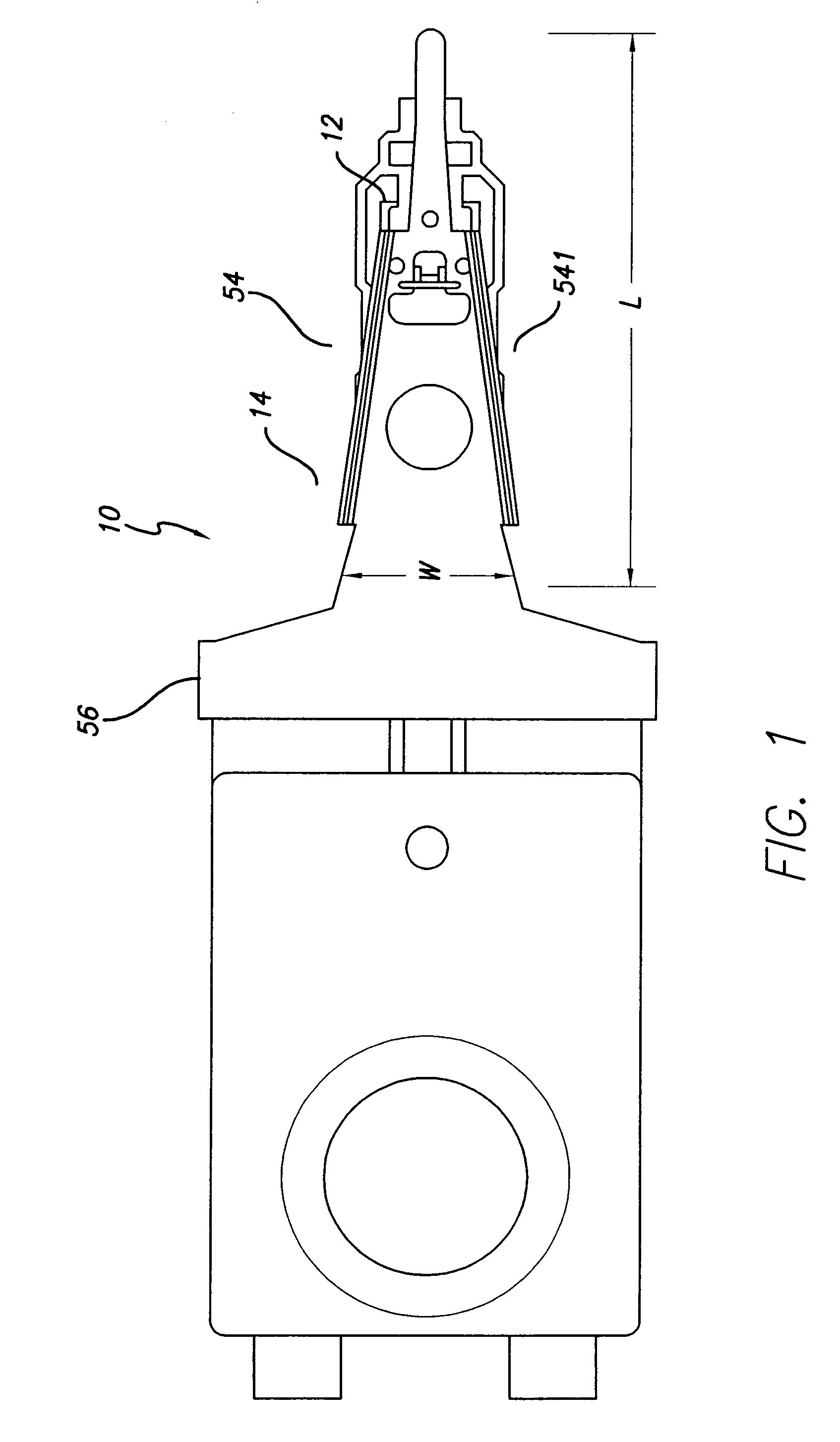
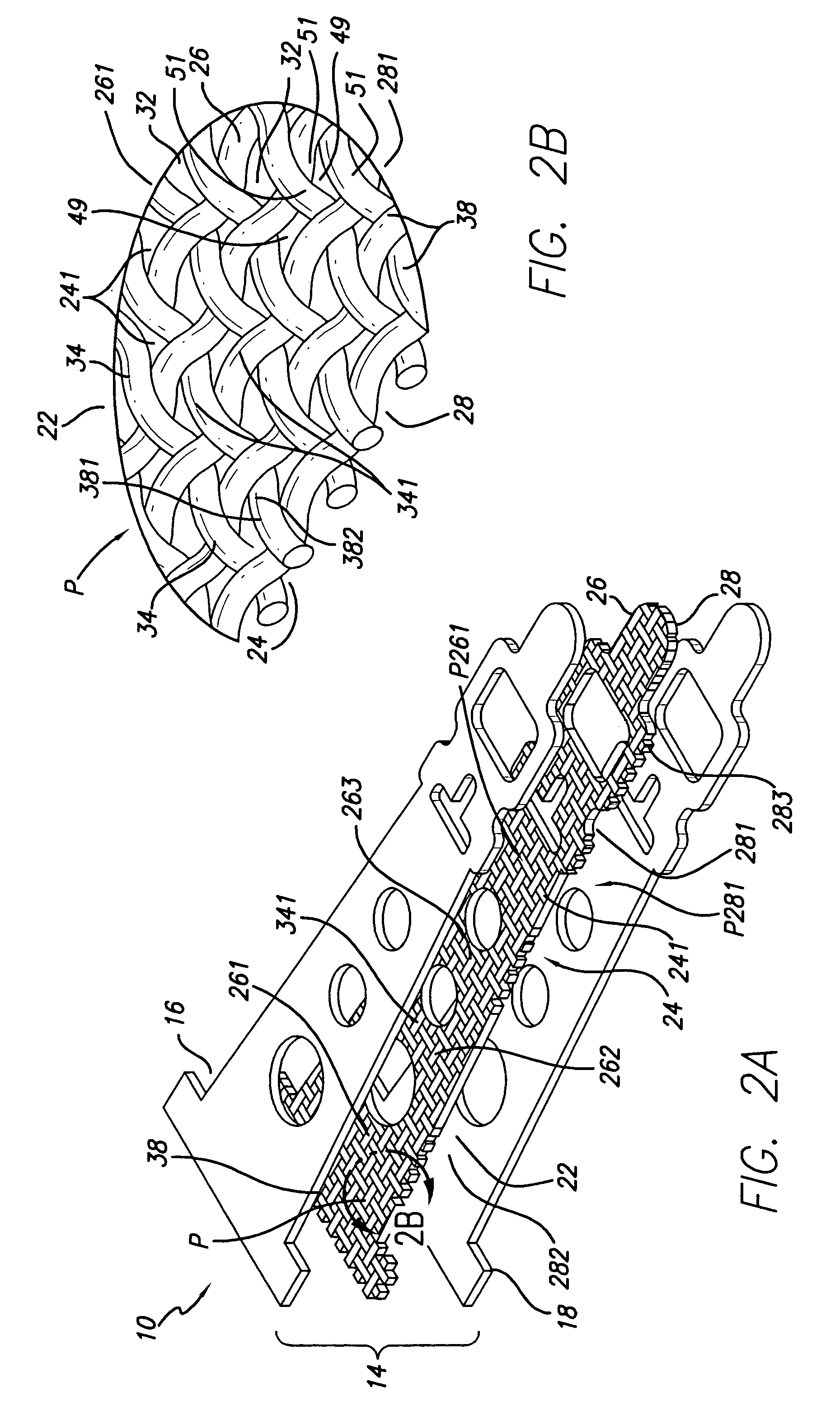
[0040]Component 10 is configured as shown as a support arm or load beam. The first and second outer layers 16, 18 are substantially planar opposite each other as shown. The intermediate layer 22 is grossly substantially planar but the local region patterns P261, P281 of discontinuities and lands define locally nonplanar surfaces 26, 28b on the intermediate layer opposite at least one of the first and second outer layers 16, 18. The intermediate layer 22 has discontinuous nonplanar surfaces 26, 28 opposite both the first and second outer layers 16, 18. Intermediate layer 22 in the first embodiment comprises multiple strands 38 arranged to define along their lengths the local region overall pattern P261, P281 of discontinuities 32 and lands 34. The intermediate layer multiple strands 38 are interfitted to define the intermediate layer 22, including being interwoven to have alternate successive portions 381, 382 of alternate interwoven strands define the lands 34 at the intermediate la...

second embodiment

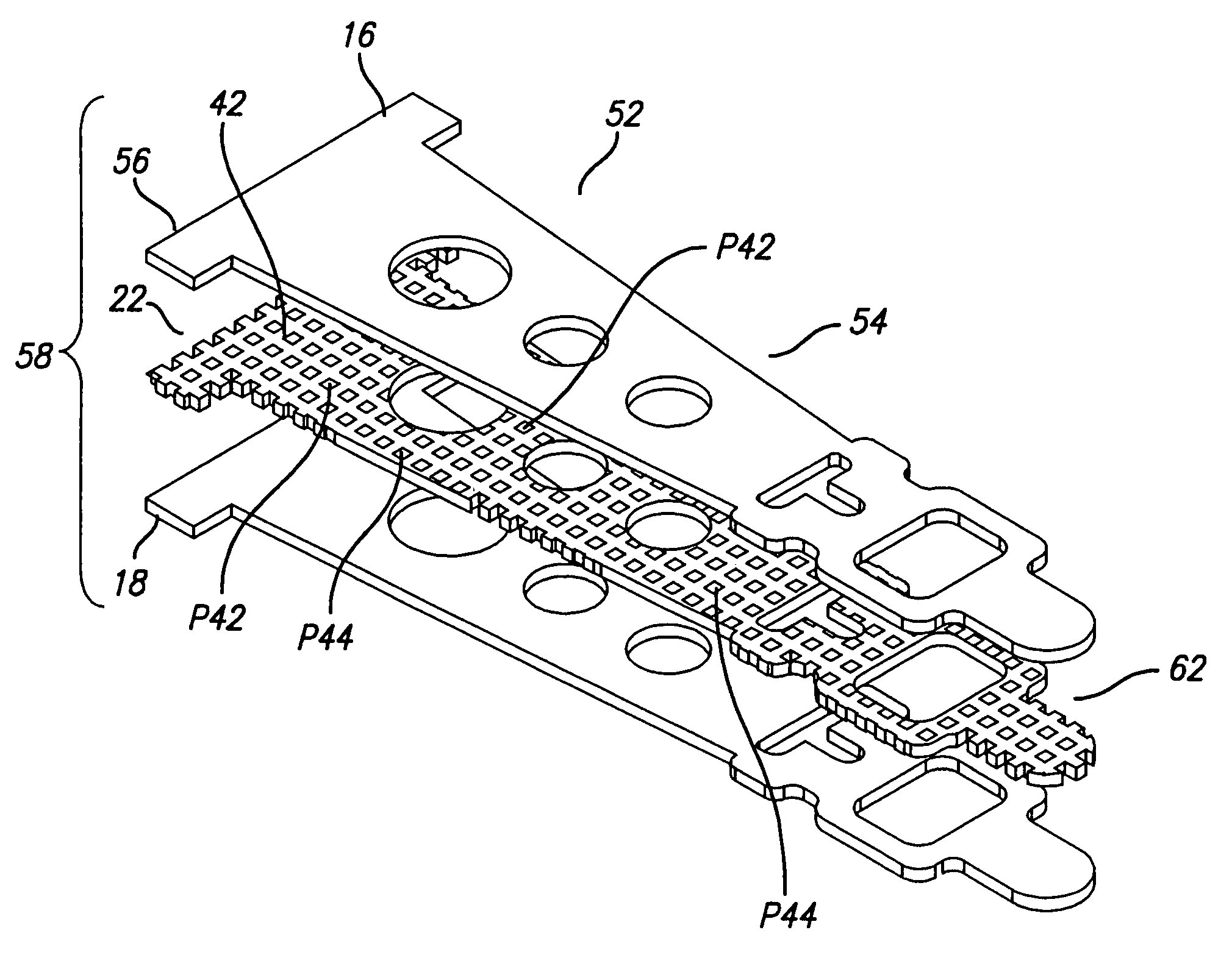
[0041]In a second embodiment, the at least one layer be it an outer layer 16, 18 or the intermediate layer 22 comprises a honeycomb panel 42 arranged to define along its length the local region overall pattern of discontinuities 32 and lands 34, e.g. the at least one layer honeycomb panel 42 can defines a multiplicity of through openings 44 and optionally a multiplicity of blind openings 46 as well as the multiplicity of through openings. Suitably, the outer layers 16, 18 in this case are typically apertured at 48 in registration with the blind openings against entrapment of liquids within the blind openings during manufacturing operations.

[0042]In a further embodiment, an assembly 52 is provided for a disk drive suspension component 10 for carrying a slider 12 at a disk. Component assembly 52 comprises a first substantially planar outer layer 16 second substantially planar outer layer 18 and a substantially planar intermediate layer 22. At least one of the layers 16, 18, 22 has a n...


PUM


Abstract

A disk drive suspension component for carrying a slider at a disk is formed of a laminate of at least three metal layers of like mechanical and chemical formability, including a first outer layer, a second outer layer, and an intermediate layer, at least one of the layers having a void-containing interior and a surface area having an undivided series of local regions distributed across substantially the width and length thereof with each local region equaling less than 10% of the surface area. Each of the local regions have an overall pattern of discontinuities and lands between the discontinuities substantially the same as the overall pattern of discontinuities and lands in laterally and longitudinally adjacent local regions for local attachment of the layers at some and not all of the lands to adjacent layers to form a laminate having common formability properties, high rigidity and light weight.

Description

CROSS-REFERENCE TO RELATED APPLICATIONS[0001]This application claims the benefit of U.S. Provisional Application Ser. No. 60 / 817,716, filed Jun. 30, 2006.BACKGROUND OF THE INVENTION[0002]1. Field of the Invention[0003]This invention relates to disk drive suspensions, and more particularly to components for such suspensions such as load beams where light weight through low equivalent density construction, and rigidity through spacing of component layers with a lower density intermediate layer for high resonance frequency applications is desired. The invention further relates to such an improved component formed of chemically and mechanically like materials such as stainless steel or aluminum in all layers for ease, convenience and lowered cost in manufacturing operations such as forming rails and etching features.[0004]2. Description of the Related Art[0005]Each suspension application has a vertical stiffness requirement for the load beam component that requires a particular stiffnes...

Claims


Application Information

Patent Timeline
IPC IPC(8): G11B5/60
CPCG11B5/484
Inventor MEI, SHIJIN
Owner MAGNECOMP
Why Eureka
Try Eureka