Ultrasonic transducer for ranging measurement with high directionality using parametric transmitting array in air and a method for manufacturing same

a transducer and high directionality technology, applied in the field of multi-resonance type ultrasonic transducers, can solve the problems of limited use of the transducer for inconvenient operation, and inability to meet the requirements of a ranging measurement using a parametric transmitting array, etc., and achieve the effect of high directionality

Inactive Publication Date: 2008-12-02
MOON WONKYU
View PDF7 Cites 36 Cited by
  • Summary
  • Abstract
  • Description
  • Claims
  • Application Information

AI Technical Summary

Problems solved by technology

The aforementioned ultrasonic transducers known so far are, however, not suitable for a ranging measurement using a parametric transmitting array.
However, there are some practical limits in use of the transducer for a ranging measurement in air.
In particular, in order to be applied to a small sized system such as a robot, the transducer needs to be very small, which does not satisfy the condition III.
Further, there is a limit on increasing the frequency difference between the two frequency components because the attenuation effect of the ultrasonic waves is in proportion to the second power of the frequency, which fails the condition IV.
However, all of the conventional ultrasonic actuators correspond to a single resonance type, thereby failing to provide a sufficient output at two frequency bands.
In addition, if an ultrasonic actuator is designed to be kept in small size, the radiation area thereof will also get small, and as a result, the output thereof will be too small.
It is, therefore, impossible to apply such actuators to a ranging measurement using a parametric transmitting array.
However, in a ranging measurement method using a parametric transmitting array, the frequency band of the ultrasonic wave primarily generated by an actuator is very different from that of the ultrasonic wave measured by a sensor.
It is, therefore, very difficult to apply such conventional sensors to a ranging measurement using a parametric transmitting array.

Method used


Image

  • Ultrasonic transducer for ranging measurement with high directionality using parametric transmitting array in air and a method for manufacturing same
  • Ultrasonic transducer for ranging measurement with high directionality using parametric transmitting array in air and a method for manufacturing same
  • Ultrasonic transducer for ranging measurement with high directionality using parametric transmitting array in air and a method for manufacturing same

Examples


Embodiment Construction

[0045]Hereinafter, preferred embodiments of the present invention will be described in detail with reference to the accompanying drawings.

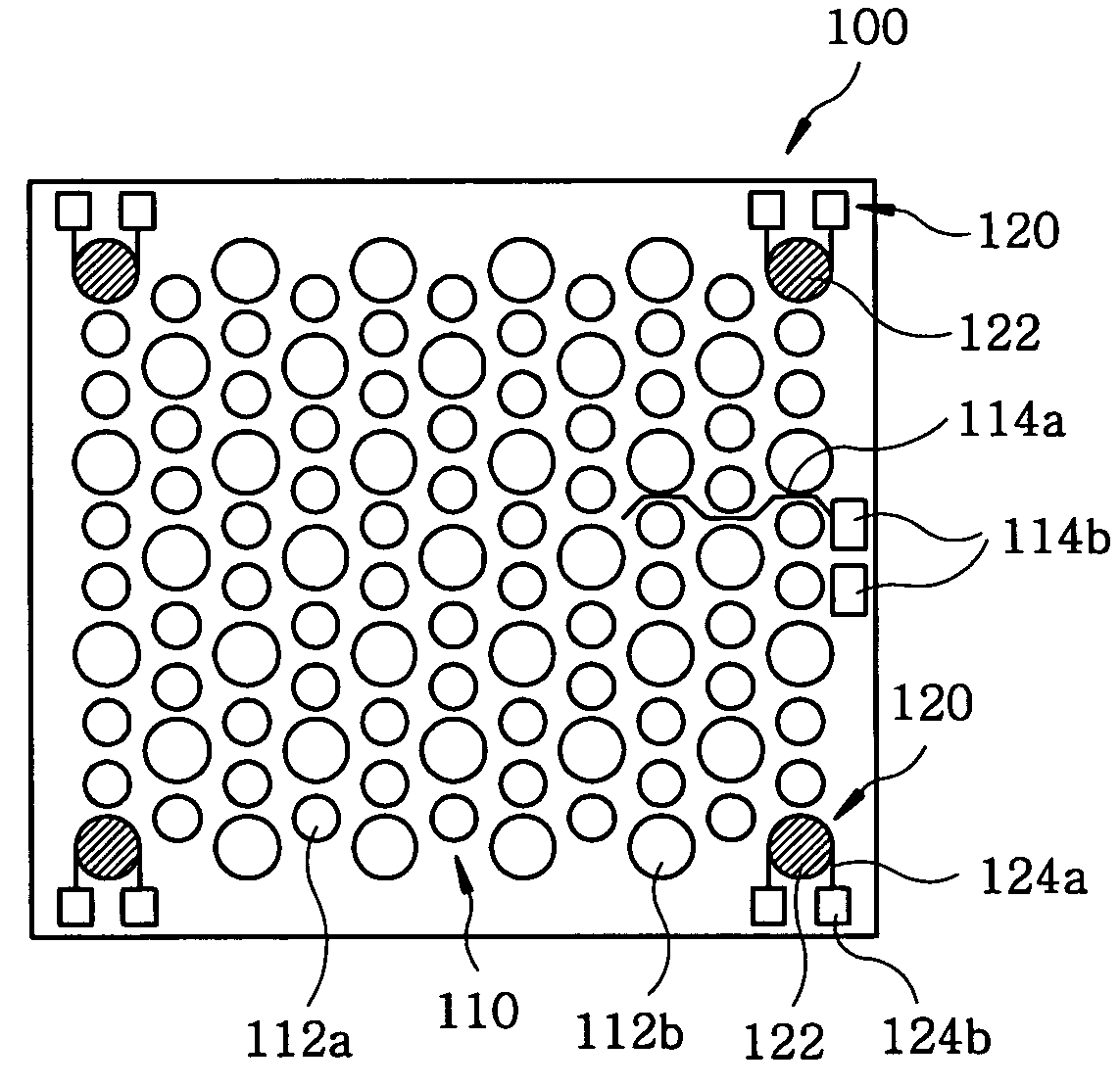
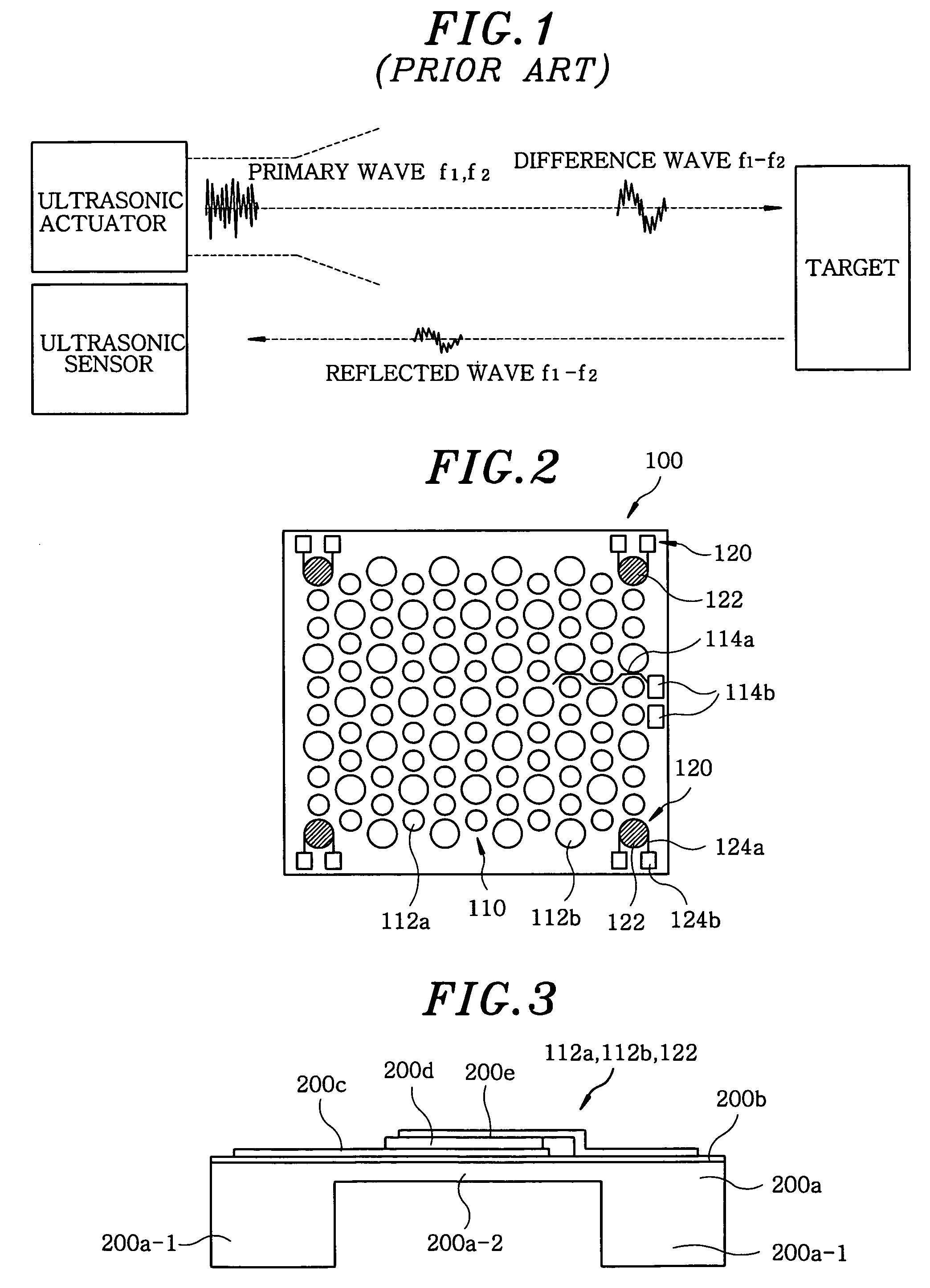
[0046]FIG. 2 is a schematic plan view showing a pMUT type ultrasonic transducer for a ranging measurement using a parametric transmitting array in accordance with the present invention.

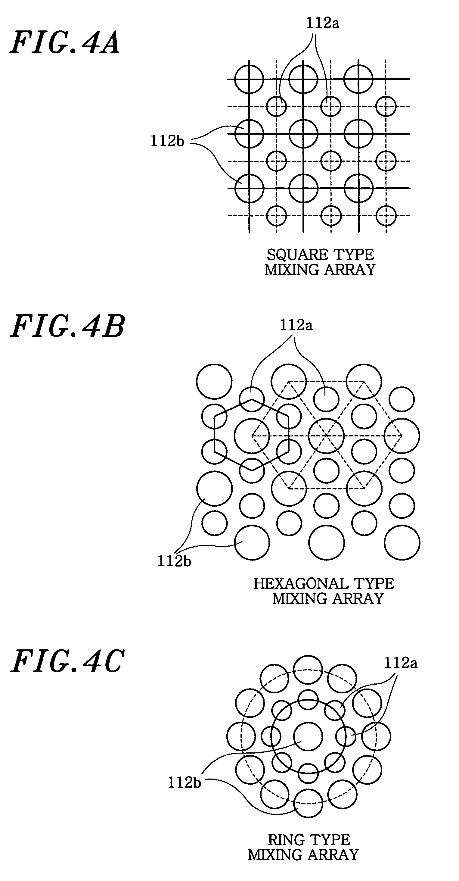
[0047]In accordance with the present invention, there is provided an ultrasonic transducer 100 having an ultrasonic actuator unit 110 and an ultrasonic sensor unit 120. The ultrasonic actuator unit 110 is formed with a mixing array of two types of small unit actuators 112a and 112b, each having a resonance frequency of f1 and f2, in order to primarily radiate the two frequency components f1 and f2 in a strong pulse type in air for a ranging measurement using a parametric transmitting array in air. Further, the ultrasonic sensor unit 120 has a resonance frequency of a difference frequency (fd=f1−f2), thereby having high sensitivity to measure a returned ultrasonic wa...


PUM


Abstract

A multiple resonances type ultrasonic transducer for a ranging measurement with high directionality using a parametric transmitting array in air, includes an ultrasonic actuator unit formed with a regularly mixing array of first unit actuators having a resonance frequency of f1 and second unit actuators having a resonance frequency of f2. The ultrasonic actuator unit generates a difference frequency wave (fd=f1−f2) with high directionality by forming a parametric transmitting array in air through generating two ultrasonic waves with high pressure in air. Further, the transducer includes an ultrasonic sensor unit formed with one or more unit sensors having a resonance frequency of the difference frequency (fd=f1−f2), for sensing a reflected ultrasonic pulse signal from a target.

Description

FIELD OF THE INVENTION[0001]The present invention relates to a multiple resonances type ultrasonic transducer based on MEMS (Micro Electro Mechanical Systems) for an ultrasonic ranging measurement with high directionality using a parametric transmitting array in air and, more particularly, to an ultrasonic transducer suitable for an ultrasonic ranging measurement using a parametric transmitting array in air.BACKGROUND OF THE INVENTION[0002]It is informed that, the present invention relates to an ultrasonic transducer applicable to Korean Patent Application No. 10-2004-0042299, “High directional ultrasonic ranging measurement system and method in air using parametric array”, commonly assigned to the applicant of the present invention and, U.S. patent application Ser. No. 10 / 960083 and Japanese Patent Application No. 2005-169938, “Ultrasonic ranging system and method thereof in air by using parametric array”, both based on a priority of the aforementioned Korean Patent Application.[00...

Claims


Application Information

Patent Timeline
Patent Type & Authority Patents(United States)
IPC IPC(8): G01S15/10
CPCB06B1/0629G01S15/102H10N30/20
Inventor MOON, WONKYULEE, HAKSUE
Owner MOON WONKYU
Why Eureka
Try Eureka