Supercharge Your Innovation With Domain-Expert AI Agents!

Information-reproducing apparatus equipped with PLL circuit

a technology of information-reproducing apparatus and circuit, which is applied in the field of information-reproducing apparatus, can solve the problems of high reducing the quality of the reproduced signal, single optical disc adversely affecting the performance of pll, and high frequency of errors in data separators, etc., and achieves high reliability and enabling information reproduction.

Inactive Publication Date: 2008-12-02
CANON KK
View PDF16 Cites 13 Cited by
  • Summary
  • Abstract
  • Description
  • Claims
  • Application Information

AI Technical Summary

Benefits of technology

This approach allows for reliable signal reproduction by stabilizing the PLL circuit, reducing errors and maintaining synchronism despite variations in signal quality and external disturbances, thereby enhancing the reliability and accuracy of data retrieval.

Problems solved by technology

As information on an optical disc increases in density, a signal recorded on the optical disc, i.e., recording mark, becomes finer, which highly reduces the quality of a reproduced signal.
Variations in quality of reproduced signals for each optical disc or within a single optical disc adversely affect PLL performance.
At worst, a loop becomes too unstable to keep following PLL, or tractability of a loop degrades and lowers synchronism between the clock and the reproduced signal, which causes high frequency of errors in the data separator 10.
A change in inclination of an edge is represented as changes in sensitivity of phase difference detection, similarly as changes in amplitude of a reproduced signal, which result in an unstable PLL as described above.
In general, the higher-density an optical disc is recorded, the worse S / N and jitter for a reproduced signal in comparison with the lower-density recording, thus, the worse a tractability of PLL.
Dust or a scratch on a surface of a disc often affects a reproduced signal, which in turn will be a disturbance to PLL.
However, in the structure of Japanese Patent Application Laid-Open No. 6-76486, characteristics of a PLL circuit have already fixed when the optical disc apparatus is designed, thus, it cannot deal with variations in amplitude of a reproduced signal and inclination of an edge caused by variations in quality of optical discs.
This results in various loop gains of PLL, and at worst, it caused problems where a loop becomes too unstable to keep following PLL, or tractability of a loop degrades and lowers synchronism between a clock and a reproduced signal, which causes high frequency of errors in a data separator.

Method used


Image

  • Information-reproducing apparatus equipped with PLL circuit
  • Information-reproducing apparatus equipped with PLL circuit
  • Information-reproducing apparatus equipped with PLL circuit

Examples


first embodiment

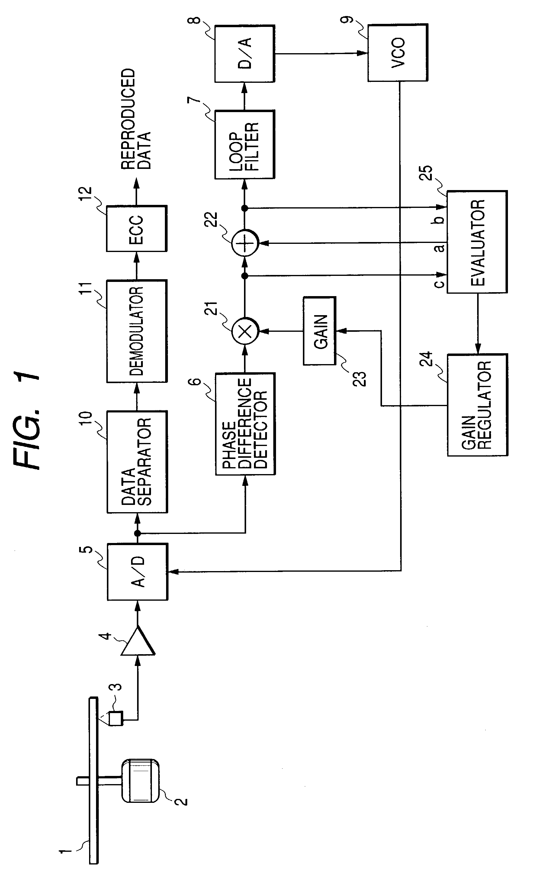
[0042]FIG. 1 is a block diagram showing a configuration of the first embodiment of the present invention. In FIG. 1, the same numerals designate the same parts as those of a conventional apparatus shown in FIG. 18 and description of them is omitted. In FIG. 1, reference numeral 21 denotes a multiplier, which multiplies an output from phase difference detector 6 by a gain set value stored in a gain 23 and outputs the result. Reference numeral 22 denotes an adder, which adds an output from an evaluator 25 to an output from the multiplier 21 and outputs the result.

[0043]The evaluator 25 is for measuring PLL loop characteristics with a port “a” for outputting a sine wave for measurement, ports “b” and “c” for inputting signals before and after addition at the adder 22. Reference numeral 24 is a gain regulator, which sets a gain set value in the gain 23 on the basis of the result from the evaluator 25 and changes a gain of PLL.

[0044]Now, operations of the present embodiment will be descr...

second embodiment

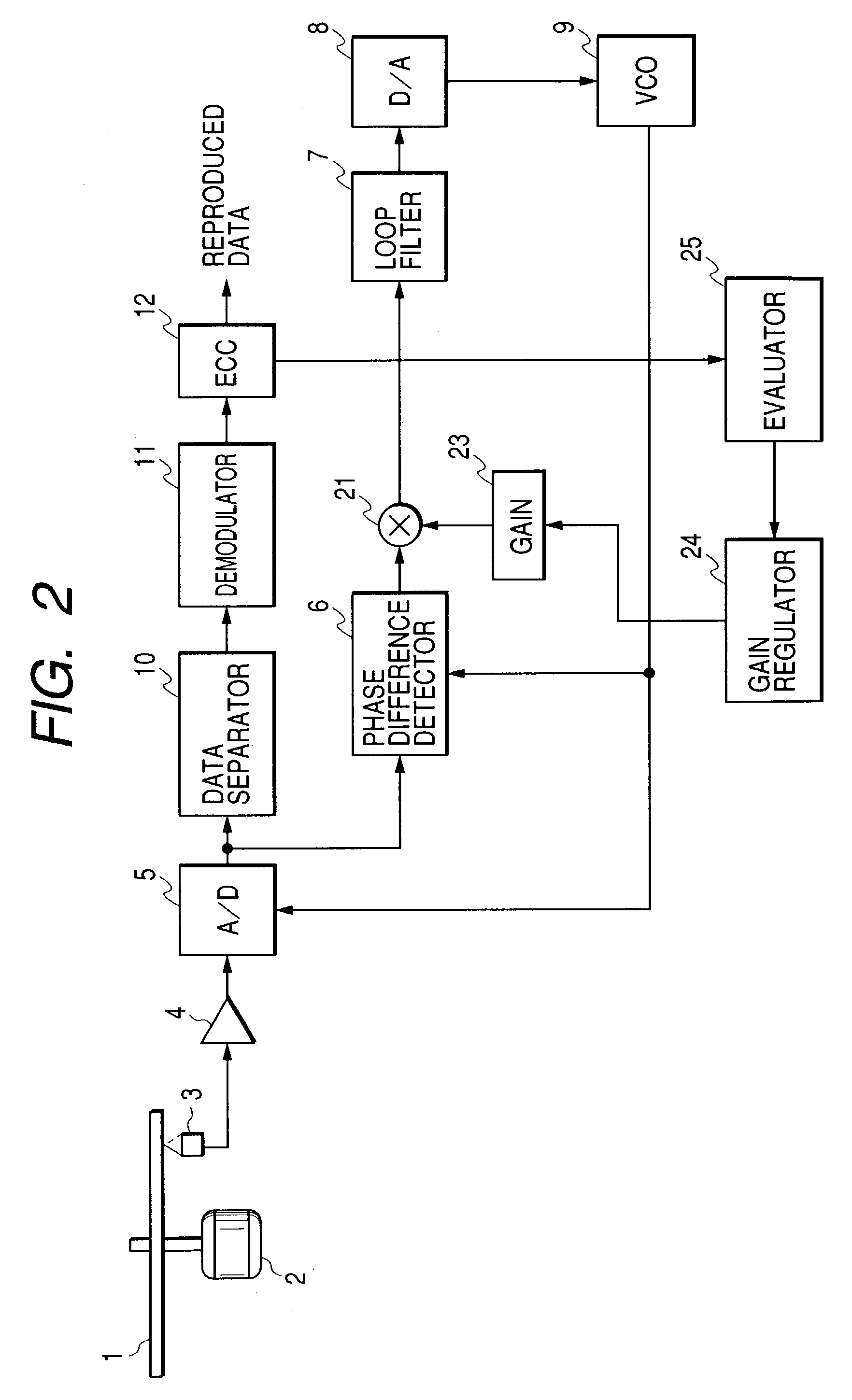
[0049]FIG. 2 is a block diagram showing a configuration of the second embodiment of the present invention. In FIG. 2, the same numerals designate the same parts as those in FIG. 1 and description of them is omitted. In the second embodiment, a reproduced signal is processed by a data separator 10 and a demodulator 11, an error rate is detected in ECC 12, and a gain 23 is regulated according to this error rate. For example, a gain regulator 24 sets −6 dB in the gain 23 and an evaluator 25 stores the error rate measured at ECC 12. Next, the gain regulator 24 sets −4 dB in the gain 23, and the evaluator 25 stores the error rate at this moment. The gain regulator 24 changes a gain to set in the gain 23 like −6, −4, . . . , +2, +4 dB in this manner, and the evaluator 25 stores an error rate for each case in association with each set gain.

[0050]FIG. 3 shows an exemplary measurement. When a gain set in the gain 23 changes, an error rate measured at ECC 12 also changes as shown in FIG. 3, w...

third embodiment

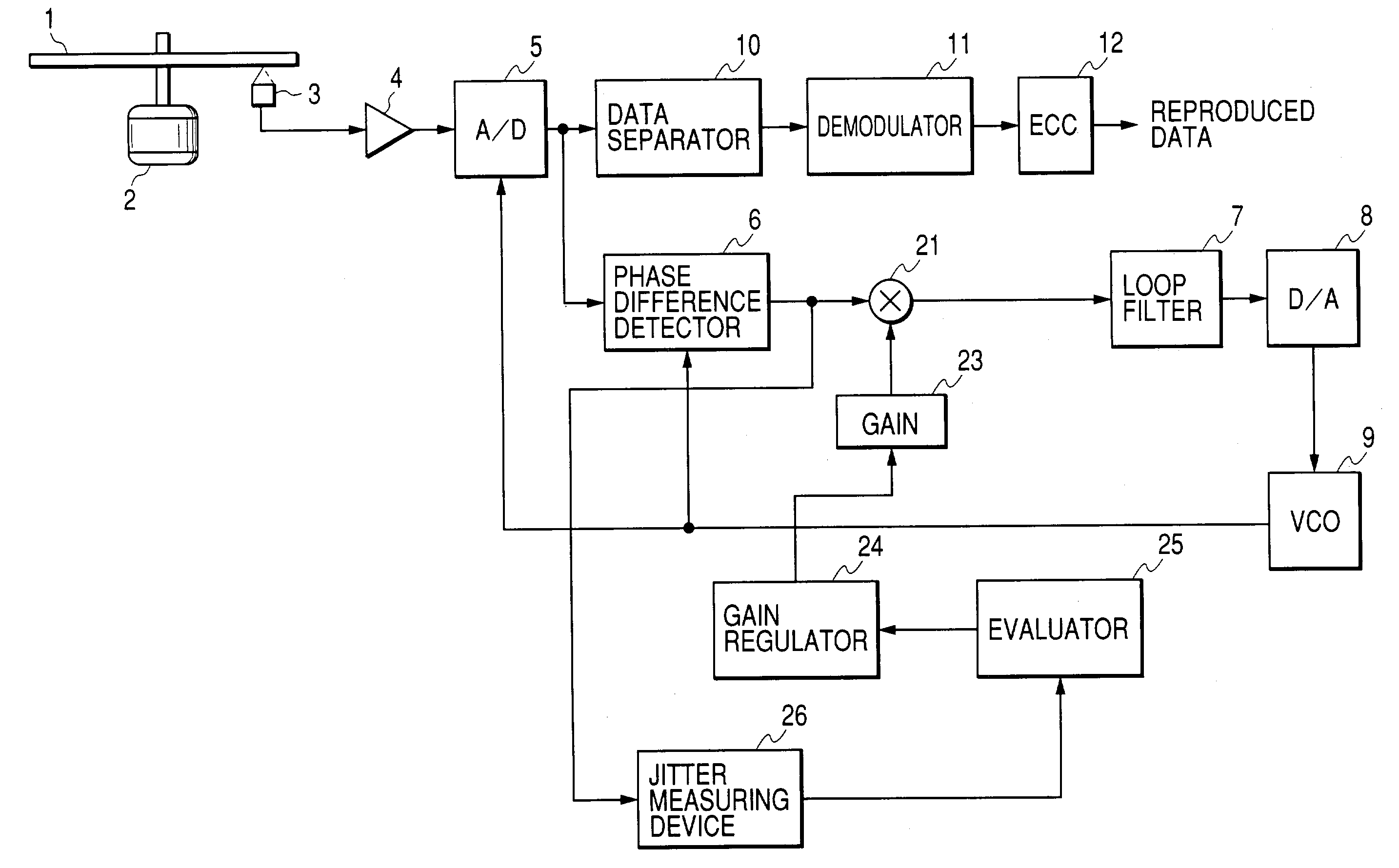
[0053]FIG. 4 is a block diagram showing the third embodiment of the present invention. In FIG. 4, the same numerals designate the same parts as those in FIG. 2 and description of them is omitted. In the third embodiment, a phase difference, which is an output from a phase difference detector 6, is used as a loop evaluation for PLL. Phase difference from the phase difference detector 6 is supplied to a jitter measuring device 26, which measures the jitter of a phase difference signal.

[0054]More specifically, at first, for example, a gain regulator 24 sets −6 dB in the gain 23. The jitter measuring device 26 measures the jitter of a phase difference at this moment, and an evaluator 25 stores the measured jitter. Next, for example, the gain regulator 24 sets −4 dB in the gain 23, and the evaluator 25 stores the jitter measured at the jitter measuring device 26 at this moment. The gain regulator 24 changes a gain to be set in the gain 23 like −6, −4, . . . , +2, +4 dB in this manner, an...


PUM

PropertyMeasurementUnit
phase difference detectoraaaaaaaaaa
phaseaaaaaaaaaa
frequencyaaaaaaaaaa

Abstract

The present invention provides highly reliable PLL without influence of variations in amplitude of a reproduced signal or variations in inclination of an edge. An information-reproducing apparatus according to the present invention includes a unit for detecting a phase difference between a reproduced signal and a reproducing clock signal, a PLL circuit for regulating a frequency of the reproducing clock signal to compensate for the detected phase difference, a unit for detecting a state of the PLL circuit, and a unit for regulating a loop gain of the PLL circuit corresponding to the detected state.

Description

BACKGROUND OF THE INVENTION[0001]1. Field of the Invention[0002]The present invention relates to an information-reproducing apparatus for reproducing digital data recorded on an information-recording medium on the basis of a reproducing clock generated by a PLL (Phase Locked Loop) circuit.[0003]2. Related Background Art[0004]FIG. 18 is a block diagram showing an example of a data recording / reproducing apparatus such as an optical apparatus. Reference numeral 1 in FIG. 1 denotes an optical disc, which is an information recording medium, 2 denotes a spindle motor for rotating the optical disc 1 at a constant speed, 3 denotes a pickup for irradiating the optical disc 1 with a light beam, receiving a reflected light from the optical disc 1 to perform photoelectric conversion, and detecting information of information track on the optical disc 1 as a reproduced signal.[0005]Reference numeral 4 denotes an amplifier for amplifying an output from the pickup 3, 5 denotes an analog-to-digital ...

Claims


Application Information

Patent Timeline
Patent Type & Authority Patents(United States)
IPC IPC(8): G11B7/005G11B20/10H03L7/08G11B20/14
CPCG11B20/10009G11B20/10083G11B20/10222G11B20/1403H03L7/08
Inventor BABA, HISATOSHI
Owner CANON KK
Features
  • R&D
  • Intellectual Property
  • Life Sciences
  • Materials
  • Tech Scout
  • Unparalleled Data Quality
  • Higher Quality Content
  • 60% Fewer Hallucinations
Learn More