Focus detection system

a detection system and focus technology, applied in the field of focus detection systems, can solve the problems of increasing the integration time and the operating time of autofocusing operation, reducing the amount of light which illuminates the light receiving surface of each line sensor, and affecting the focusing effect of the camera

Inactive Publication Date: 2008-12-02
RICOH IMAGING COMPANY
View PDF12 Cites 16 Cited by
  • Summary
  • Abstract
  • Description
  • Claims
  • Application Information

AI Technical Summary

Benefits of technology

[0008]The present invention has been devised in view of the above described problems in conventional focus detection systems and provides a focus detection system in which the integral operation can be controlled to prevent the image signal output from any line sensor from reaching a level of saturation even if monitor sensors are arranged to correspond to only a part of the line sensors.
[0009]The present invention further provides a focus detection system capable of reducing the integration time for the image in the vicinity of midrange brightness. According to an aspect of the present invention, a focus detection system is provided, including at least one line sensor array having a plurality of areas, each of which includes a plurality of pixels, wherein the line sensor array photoelectrically converts object light received by each of the plurality of pixels into electric charge to accumulate the electric charge, and outputs the accumulated electric charge as an image signal; a plurality of monitor sensor arrays, positioned so as to be adjacent to the plurality of areas of the line sensor array, for monitoring amounts of light received by the plurality of areas of the line sensor array to output monitor signals representing the amounts of light, respectively; a controller which terminates an integral operation of the line sensor array immediately after the monitor signals reach an integration termination value; and a saturation detecting device for detecting whether the image signal reaches a predetermined level of saturation. In the case where the saturation detecting device detects that the image signal reaches the predetermined level of saturation, the controller changes the integration termination value so that the monitor signals reach the integration termination value in less time, and makes the line sensor array perform the integral operation again.
[0017]According to the present invention, even if there is a line sensor array or an area whose amount of received light is not monitored by any monitor sensor array, either the amplification factor is reduced or the maximum integration time is shortened to make the line sensor array perform the integration operation again in the case where an image signal reaches a level of saturation, and a false focusing operation which may be caused by output saturation is prevented from being carried out. In the case where the maximum integration time is shortened with no reduction of the amplification factor, the time necessary for the re-integral operation is shortened, which reduces the operating time of the focusing operation.

Problems solved by technology

Accordingly, installing a plurality of monitor sensors on each line sensor or each focus detection zone has become difficult due to the limited chip size of each monitor sensor.
Due to the tendency of increasing the number of focus detection zones and miniaturization of an optical system of the autofocus (AF) system, the amount of light which illuminates the light receiving surface of each line sensor tends to decrease, i.e., there is a tendency for an object image projected onto each line sensor to become dark, which increases the integration time and the operating time of autofocusing operation.

Method used


Image

  • Focus detection system
  • Focus detection system
  • Focus detection system

Examples


Embodiment Construction

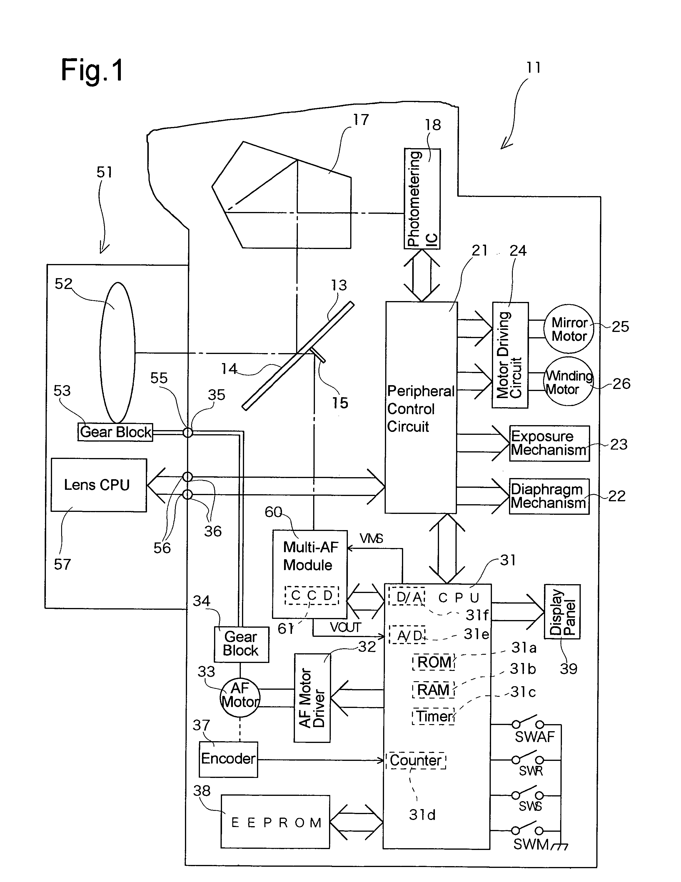
[0026]FIG. 1 shows a block diagram of the main components of an AF single-lens reflex camera to which an embodiment of the present invention is applied. The AF single-lens reflex camera includes a camera body 11 having incorporated therein a multi-AF module (multipoint focus detection module) 60 with a CCD focus detection element 61, as a focus detection element, and an AF photographing lens 51 detachably attached to the camera body 11. The camera body 11 includes a body CPU 31 which generally controls the camera body 11 and the photographing lens 51, and which functions also as a selection device, a discrimination device, and a reliability judging device.

[0027]The photographing lens 51 is provided with a lens CPU 57 which controls the lens function. The camera body 11 includes a peripheral control circuit 21 which receives and transmits lens data and AF lens driving data, etc., from and to the lens CPU 57 provided in the photographing lens 51.

[0028]A large part of an object light b...


PUM


Abstract

A focus detection system includes a line sensor array having areas including pixels, wherein the line sensor array photoelectrically converts object light received by each pixel into electric charges, and outputs accumulated electric charges as an image signal; monitor sensor arrays, adjacent to the areas of the line sensor array, for monitoring amounts of light received thereby to output monitor signals, respectively; a controller which terminates an integral operation of the line sensor array immediately after the monitor signals reach an integration termination value; and a saturation detecting device for detecting whether the image signal reaches a predetermined level of saturation. If the saturation detecting device detects that the image signal reaches the predetermined level of saturation, the controller changes the integration termination value so that the monitor signals reach the integration termination value quicker, and makes the line sensor array perform the integral operation again.

Description

BACKGROUND OF THE INVENTION[0001]1. Field of the Invention[0002]The present invention relates to a focus detection system which is incorporated in optical equipment such as an SLR camera.[0003]2. Description of the Related Art[0004]In a conventional phase difference focus detection system incorporated in an SLR camera system to serve an autofocus (AF) system thereof, a pair of object images obtained by pupil division are projected onto a pair of areas on a line sensor (line sensor array) to be converted into a pair of electric charges (electrical signals) by the line sensor, and the pair of electric charges are converted as a pair of image signals, respectively. Thereafter, a phase difference between the pair of object images formed on the line sensor is determined according to the pair of image signals, and a focus state (defocus amount) is determined based on the phase difference.[0005]In the case where such a focus detection system is a multipoint focus detection system capable o...

Claims


Application Information

Patent Timeline
Patent Type & Authority Patents(United States)
IPC IPC(8): G03B3/00H04N3/14
CPCG02B7/08G02B7/34G03B17/02G03B19/12H04N5/2251H04N5/23209H04N5/23212H04N23/663H04N23/672
Inventor NAKATA, MASAHIRO
Owner RICOH IMAGING COMPANY
Why Eureka
Try Eureka