Laser projection system, intelligent data correction system and method

a technology of intelligent data correction and laser projection, applied in the field of laser projection system, intelligent data correction system and method, can solve the problems of serious problem, inability to accurately position the laser image projected by the laser projector(s) on the workpiece, etc., and achieve the effect of accurate positioning

Active Publication Date: 2008-12-09
NIKON METROLOGY
View PDF12 Cites 86 Cited by
  • Summary
  • Abstract
  • Description
  • Claims
  • Application Information

AI Technical Summary

Benefits of technology

[0009]As set forth above, the intelligent data correction system with a laser projection system and method of this invention modifies or “corrects” the data stored in the computer associated with the laser projection of the as-designed condition of the workpiece to provide for accurate projection of a laser image or template on the workpiece in the as-built condition. The laser projection system including an intelligent data correction system of this invention comprises a digitizing system or digital scanner, preferably a 3D digital scanner, which determines the as-built condition of the workpiece, a computer receiving data of an as-designed condition of the workpiece and receiving data from the digitizing system of the as-built condition of the workpiece, and / or data of the laser projection to be projected on the target workpiece based upon the as-designed condition of the target workpiece. The computer then compares the data of the as-built condition of the target workpiece with the data of the as-designed condition of the target workpiece and modifies or “morphs” the data to correspond to the data of the as-built condition of the workpiece. That is, the computer receives data of the as-built condition of the target workpiece from the digitizing system and a data file either of the as-designed condition of the target workpiece, the laser projection to be projected on the target workpiece based upon the as-designed condition of the workpiece or both, depending upon the application. In some applications, all that will be required is to import the data of the laser projection based upon the as-designed condition for correction of the laser projection. However, in one preferred embodiment, the computer receives data of the as-designed condition of the workpiece and compares the data of the as-built condition of the workpiece received from the digitizing system and corrects or morphs the data of the as-designed condition of the workpiece. The data of the as-designed condition of the workpiece and the data of the laser projection to be projected on the workpiece may be the same file. Finally, the laser projector projects a laser image or laser template on the target surface based upon the data received from the computer regarding the as-built condition of the target workpiece. The laser image or laser template is thus accurately positioned on the target workpiece based upon the as-built condition of the workpiece without requiring laborious input of further data to the computer of the modifications made to the target workpiece.
[0011]In a preferred embodiment, the method of projecting a laser image on a target workpiece of this invention based upon the as-built condition of the target workpiece thus comprises first determining an as-built condition of the target workpiece with a digitizing system preferably by scanning the target workpiece and storing this information in a computer, preferably a computer associated with the laser projector. The computer may then compare the data of the as-built condition of the workpiece with data of the as-designed condition of the workpiece previously stored and modifies or corrects the data of the as-designed target workpiece to the data of the as-built condition of the target workpiece. Alternatively, the data of the laser projection based upon the as-designed condition may be sufficient. As set forth above, the method of this invention also includes storing data in the computer of a laser image to be projected on the target workpiece based upon the as-designed condition of the target workpiece and the computer then modifies the data of the laser image based upon the corrected data regarding the as-built condition of the target workpiece. Finally, the method of this invention includes controlling the laser projector to project a laser image at the predetermined location or locations and orientation on the target workpiece based upon the corrected data received from the computer of the as-built condition of the workpiece. Thus, the method of this invention correctly and accurately projects a laser image or laser template on the target workpiece based upon the as-built condition of the workpiece, including but not exclusively, modifications made to the workpiece during assembly, without requiring laborious input of further data regarding the differences between the as-designed condition of the workpiece and the actual as-built condition.

Problems solved by technology

However, in certain applications, the “as-built” condition of the workpiece differs from the “as-designed” condition to such a degree that the laser image projected by the laser projector(s) will not be positioned correctly on the workpiece.
This can be a serious problem particularly, but not exclusively, for larger workpieces subject to modification to accommodate customer requirements.

Method used


Image

  • Laser projection system, intelligent data correction system and method
  • Laser projection system, intelligent data correction system and method
  • Laser projection system, intelligent data correction system and method

Examples


Embodiment Construction

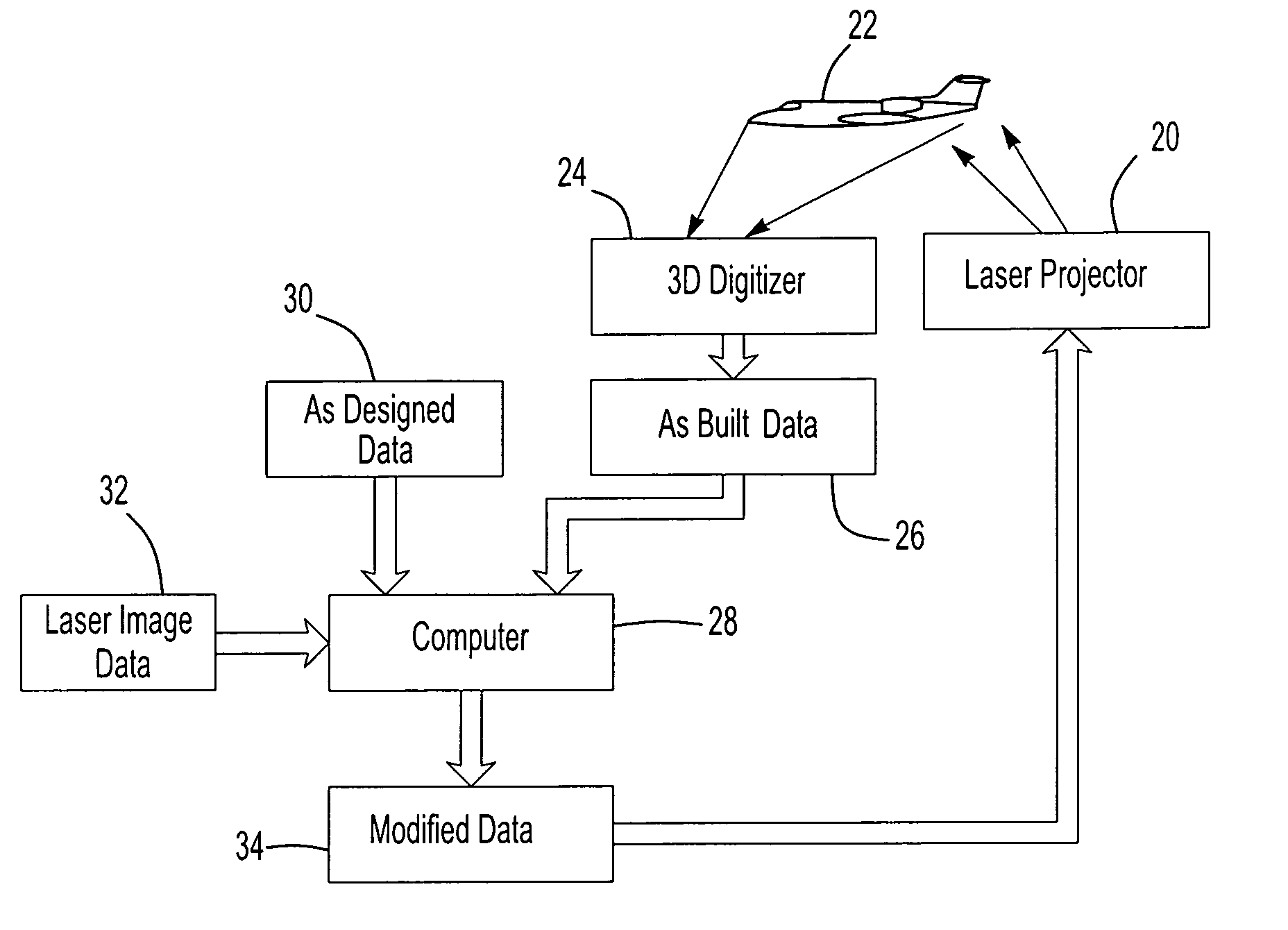
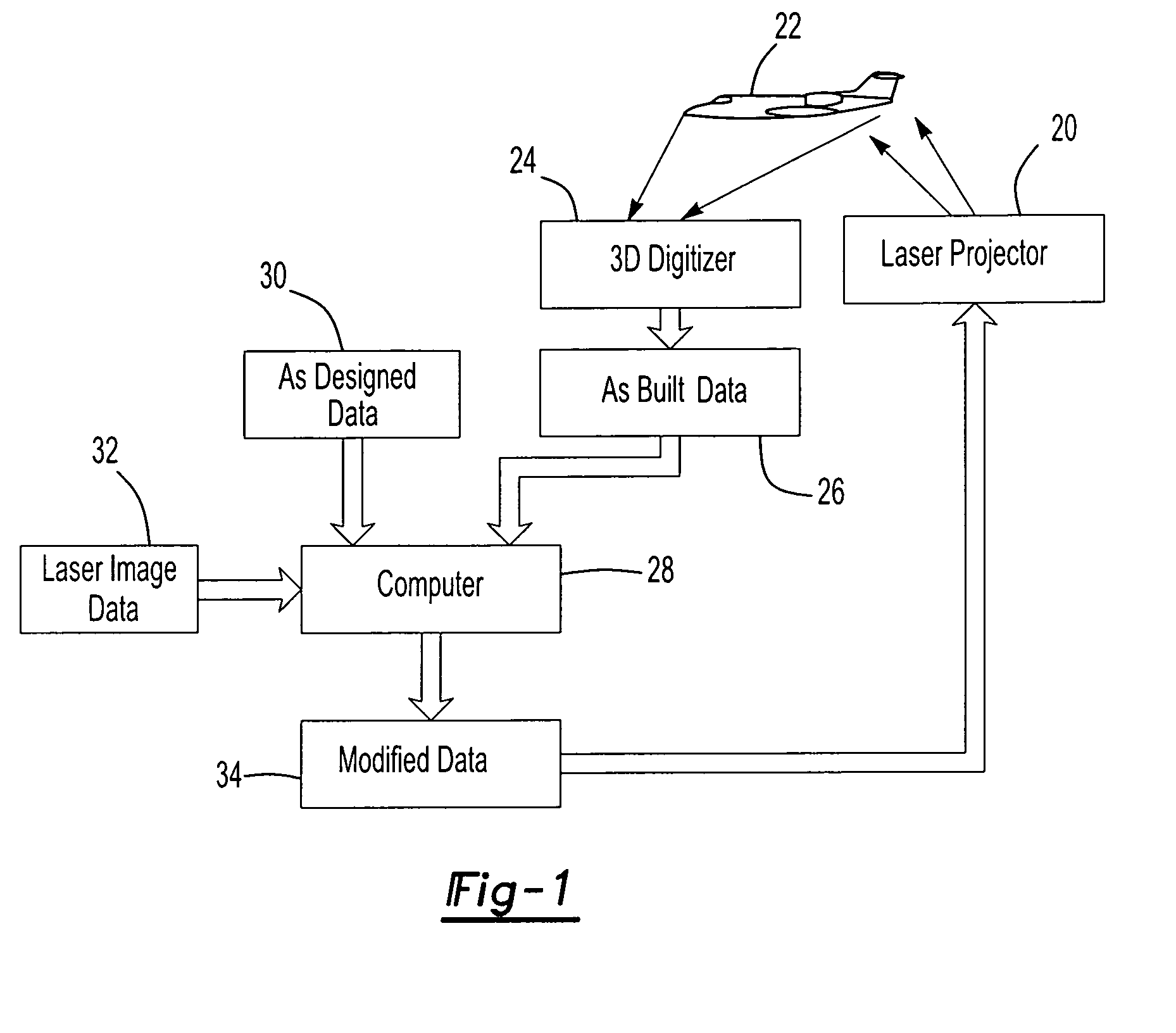
[0020]FIG. 1 may be characterized as a flow chart or block diagram illustrating a laser projection system having an intelligent data correction system and method of this invention, wherein a laser projector 20 is adapted to project a laser image, outline template on a target surface of a workpiece 22 which, in the illustrated embodiment, is an aircraft. As set forth above, the laser projection system of this invention may be utilized for projecting a laser image on any workpiece, but is particularly useful for projecting a laser image at a predetermined location and orientation on large workpieces subject to modification during construction or assembly, such that the as-built condition of the target workpiece differs from the as-designed condition of the workpiece. The first step in the method of this invention is to scan the workpiece or a predetermined portion of the workpiece with a 3D digitizing system or digitizer scanner 24, preferably a noncontact digitizer scanner, to determ...


PUM

PropertyMeasurementUnit
projection angleaaaaaaaaaa
flexibilityaaaaaaaaaa
Phase shift techniqueaaaaaaaaaa

Abstract

A laser projection system, intelligent data correction system and method which corrects for differences between the as-built condition and the as-designed condition of a workpiece which includes determining the as-built condition of a workpiece with a digitizer scanner and modifying data of the as-built condition or the data of a laser projection based upon the data received from the digitizer scanner of the as-built condition. A preferred intelligent data correction system includes metrology receivers fixed relative to the digitizer scanner and the workpiece and a metrology transmitter to determine the precise location and orientation of the digitizer scanner relative to the workpiece.

Description

RELATED APPLICATION[0001]This application is a continuation-in-part of U.S. patent application Ser. No. 10 / 913,842, filed Aug. 6, 2004, which claims priority to U.S. Provisional Patent Application Ser. No. 60 / 501,885, filed Sep. 10, 2003.FIELD OF THE INVENTION[0002]This invention relates to a laser projection system, an intelligent data correction system and method of projecting a laser image or template on a target workpiece, wherein the laser projection system and method corrects for discrepancies between the target workpieces as-designed condition and the target workpieces as-built condition.BACKGROUND OF THE INVENTION[0003]Visible laser projection systems are now widely used in the industry to project a laser outline, laser image or laser template on a target surface or workpiece for assembling large two or three-dimensional structures or assemblies, such as prefabricated roof trusses and aerospace composite components. By precisely characterizing the laser projector and establi...

Claims


Application Information

Patent Timeline
Patent Type & Authority Patents(United States)
IPC IPC(8): G01B11/14B23K26/00F41G3/26
CPCB25H7/00G05B2219/32189G05B2219/36251G05B2219/37097G05B2219/37555Y02P90/02
Inventor MORDEN, JARRAD V.RUEB, KURT D.
Owner NIKON METROLOGY
Why Eureka
Try Eureka