Pipe joint

a pipe joint and pipe technology, applied in the direction of hose connections, bends, clutches, etc., can solve the problems of inability to ensure the safety of the retainer and the inability of the conventional pipe joint to be a general-purpose item, and achieve the effect of improving assembly efficiency

Active Publication Date: 2008-12-16
TOGO SEISAKUSYO CORP
View PDF11 Cites 55 Cited by
  • Summary
  • Abstract
  • Description
  • Claims
  • Application Information

AI Technical Summary

Benefits of technology

[0009]In the above-described construction, since a plurality of the sliding surfaces is formed so as to extend peripherally about an outer face of the support, the selection of a plurality of fitting positions between the support and the guide is possible. Accordingly, the mounting angle of the retainer to the relative to the pipe joint can be adjusted by changing the fitting position of the support. More specifically, since a direction of operation of the retainer can be selected irrespective of the direction of extension of the tubing connector, the retainer can be mounted without having to use a forced or difficult assembly position, improving the assembly efficiency.

Problems solved by technology

Accordingly, when a single type of pipe joint is used in a plurality of applications, there often arises a case where a space for operating (i.e., thrusting the retainer into the locked position) the retainer cannot be ensured.
This illustrates the problem that the conventional pipe joint lacks the ability of being a general-purpose item.

Method used


Image

  • Pipe joint
  • Pipe joint
  • Pipe joint

Examples


first embodiment

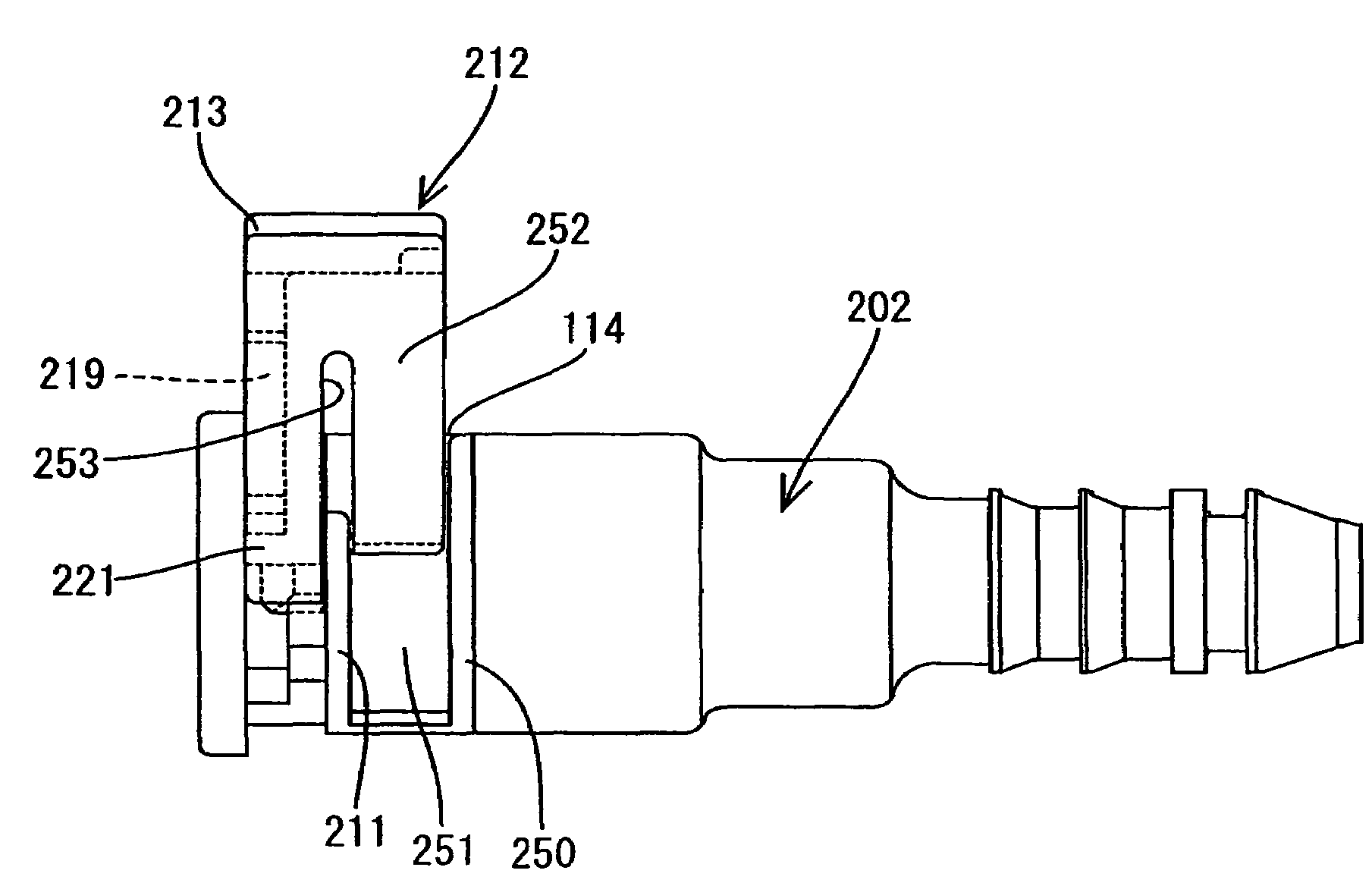
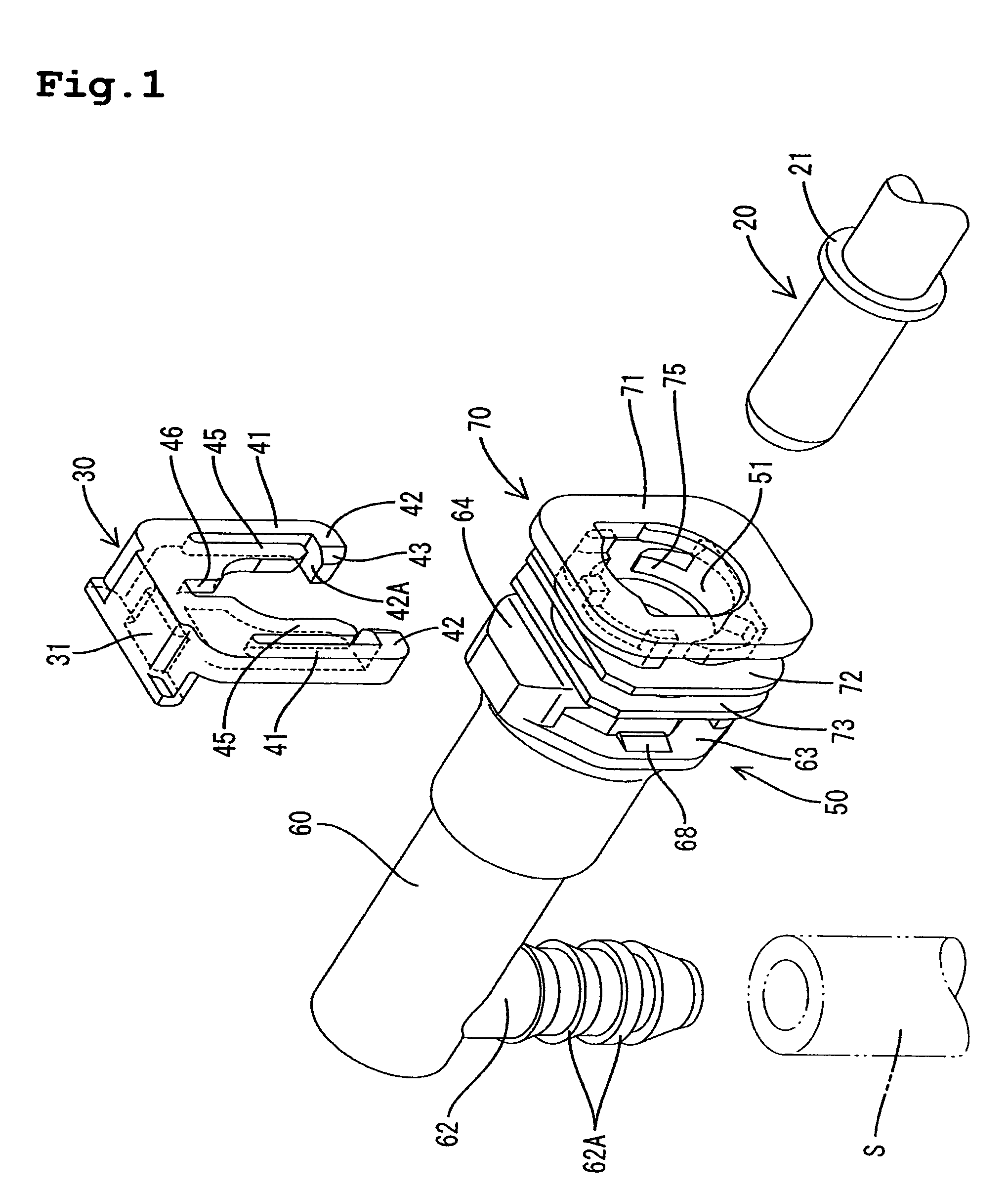
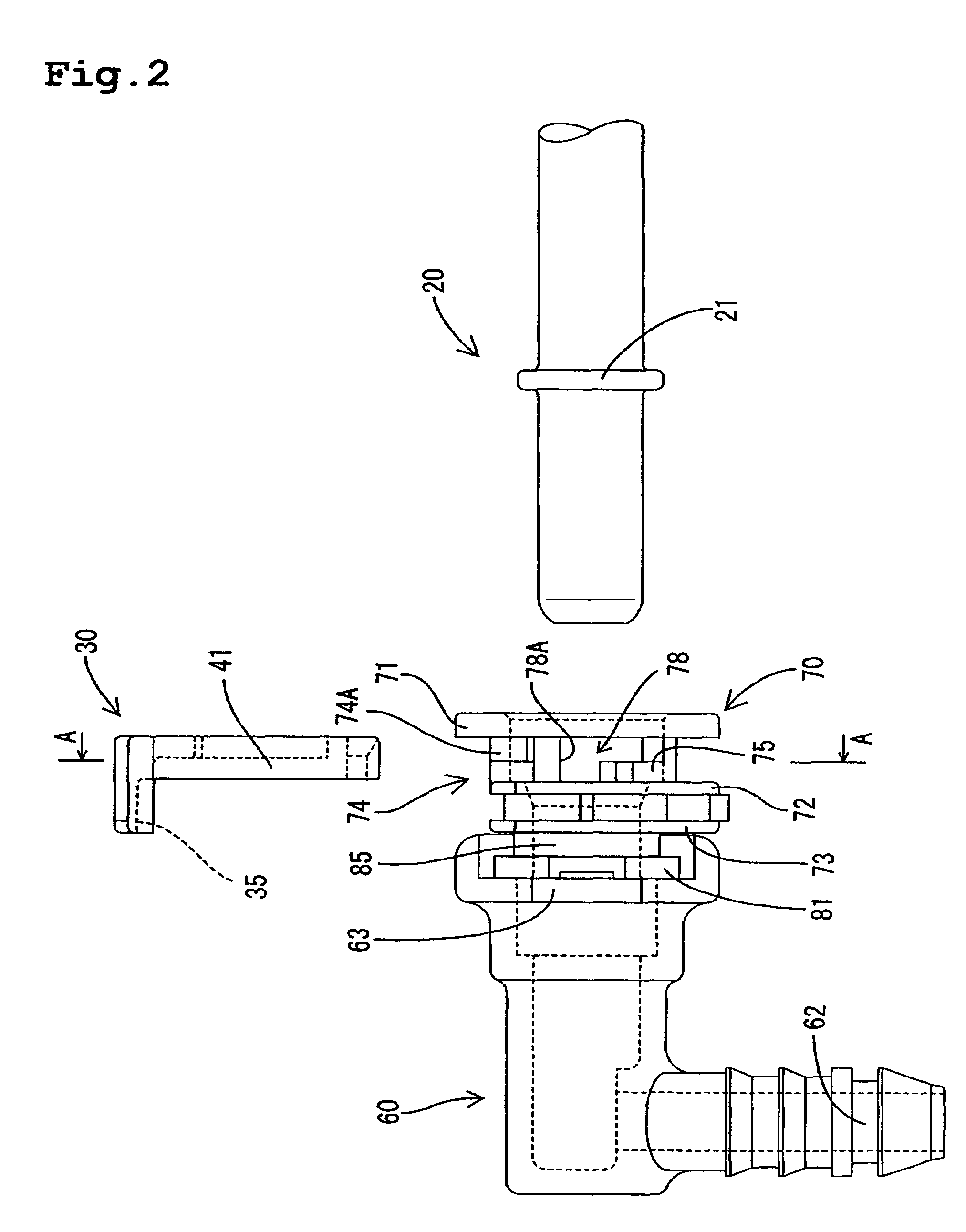
[0051]Several embodiments of the present invention will be described. FIGS. 1 to 16 illustrates the pipe joint of a Referring to FIG. 1, a rigid pipe 20 is made of a synthetic resin or a metal for example. A retaining flange 21 is formed on a distal end of the rigid pipe 20 so as to extend about the entire periphery of the rigid pipe 20. A pipe joint body 50 is divided into front and rear components as will be described later. The front component is a tube connector 60 serving as a first piping connector in the invention. The second component is a rigid pipe connector 70 serving as the second piping connector. A flexible tube S is adapted to be connected to the tube connector 60. A retainer 30 and the rigid pipe 20 are adapted to be connected to the rigid pipe connector 70. In FIG. 1, the left side is the front and the right side is the rear.

[0052]The pipe joint body 50 includes a tube-fitting portion 62 formed on an end of a cylindrical portion and bent at some angle downward (in ...

fourth embodiment

[0081]FIGS. 20 to 30 illustrate the invention. Referring to FIG. 20, a rigid pipe P is made of a synthetic resin or a metal. A retaining flange 101 is formed in a distal end of the rigid pipe P so as to extend about the entire periphery. A pipe joint body 102 is made of a synthetic resin into a generally right cylindrical shape. The pipe joint body 102 has a distal end formed with a tube connector 104 having a plurality of engaging protrusions 103. A tube T is connectable to the tube connector 104. Furthermore, the pipe joint body 102 has a bore 105 formed therein so as to extend axially through the pipe joint body 102. The rigid pipe P is adapted to be inserted into the bore 105.

[0082]A stepped portion 106 is formed in a boundary between the bore 105 and a portion corresponding to the tube connector 104. The bore 105 has an entrance with stepped portion including a larger diameter. Two O-rings 107, a spacer 108, and an O-ring presser 109 are inserted in the larger diameter portion ...

fifth embodiment

[0104]The operation and advantages of the pipe joint of the fifth embodiment will now be described. The rigid pipe P is initially inserted into the bore 105 after the retainer 112a has been located in the preliminary lock position. When the rigid pipe P reaches the insertion depth, the engagement arms 121 are spread apart such that the engagement claws 122 are disengaged from the stepped portions 123 (the state as shown in FIG. 32). In this condition, the operator presses the upper face of the base of the retainer 112a and forces the retainer 112a together with the checker 115a into the side of the pipe joint body 102a. The engagement claws 122 are then brought into sliding contact with the outer faces of the stepped portions 123. When the retainer 112a has reached the final locking position, the detecting piece 121 is resiliently restored towards the original configuration and the engagement claws 122 engage the underside of the pipe joint body 102a. In this case, the locking piece...


PUM


Abstract

A pipe joint for connecting a rigid pipe with a retaining flange to a tube includes a pipe joint body formed with a through bore and a window in communication with the bore. A tube connector portion may be connected at an angle to a rigid pipe connector portion. A pipe retainer provided with locking pieces can be located in two positions relative to the pipe joint body. The first position allows the retaining flange to pass through the locking pieces. The second position retains the rear of the retaining flange and prevents inadvertent removal of the rigid pipe. The retaining pieces engage the rear of the flange through the window communicating with the bore. The locking direction of the retainer can be altered relative to the tube connector portion to suit different applications and ease assembly.

Description

BACKGROUND OF THE INVENTION[0001]1. Field of the Invention[0002]This invention relates to a pipe joint for connecting a rigid pipe to a flexible tube, for example, as used in automobiles.[0003]2. Description of the Related Art[0004]Pipe joints have been known as means for connecting a rigid fuel pipe (typically a metal fuel pipe or resin tube) to a flexible tube where each component has a relatively small diameter. The pipe joint may be used for example in the fuel supply system of an automobile. JP-A-10-509232 discloses one of these types of pipe joints. In the disclosed pipe joint, a tube connector (a male connector) is fitted to a pipe joint body (a female connector) to which a rigid (metal or resin for example) pipe is connectable. A retainer further fixes or locks the fitted rigid pipe to prevent inadvertent or unintentional removal of the rigid pipe. The pipe joint body has a bore into which the rigid pipe is inserted. A side hole is formed in an outer face of the pipe joint b...

Claims


Application Information

Patent Timeline
Patent Type & Authority Patents(United States)
IPC IPC(8): F16D37/00F16L37/098F16L37/14F16L37/26
CPCF16L37/0982F16L37/0985F16L37/144F16L37/26F16L2201/10
Inventor YAMADA, YUJIOI, SHIGEONONOYAMA, NAOHITO
Owner TOGO SEISAKUSYO CORP
Why Eureka
Try Eureka