DC-AC converter, controller IC therefor, and electronic apparatus utilizing such DC-AC converter
a dc-ac converter and controller technology, applied in the direction of electric variable regulation, process and machine control, instruments, etc., can solve the problems of difficult downward extension of the lower limit of dimmer control of the load in the form of a ccfl, difficult to perform fine dimmer control using the inverter, and limit the reduction of pulse width, so as to reduce the hamming caused by intermittent operation of the transformer, reduce the hamming, and prevent over-
- Summary
- Abstract
- Description
- Claims
- Application Information
AI Technical Summary
Benefits of technology
Problems solved by technology
Method used
Image
Examples
first embodiment
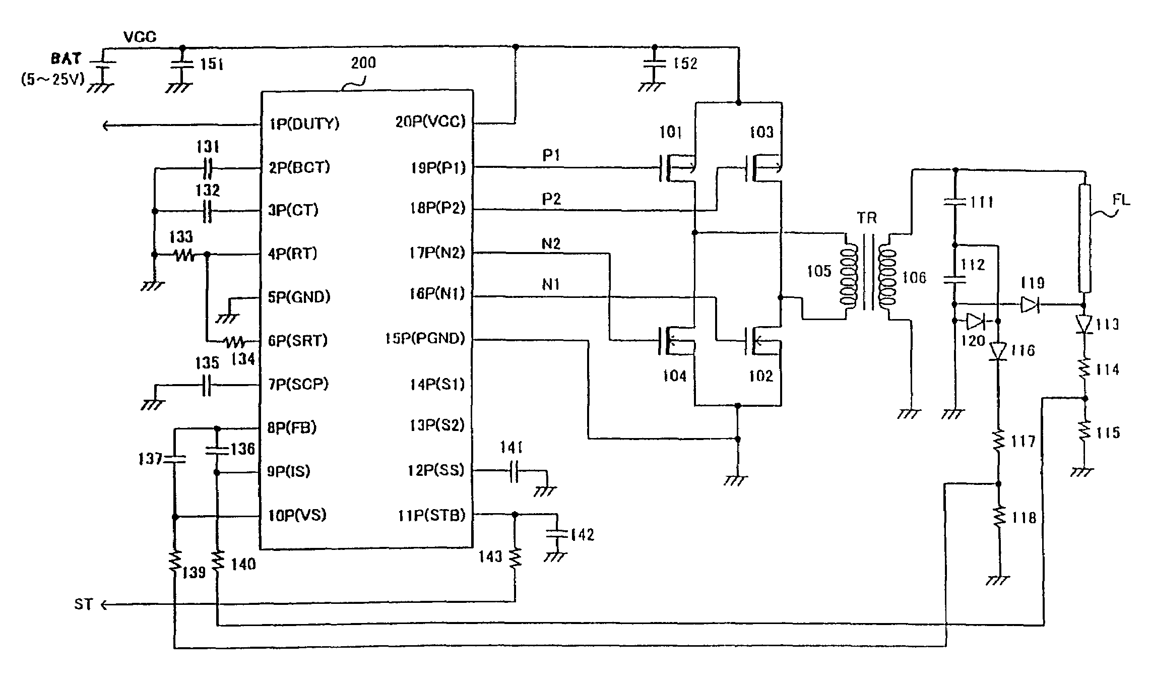
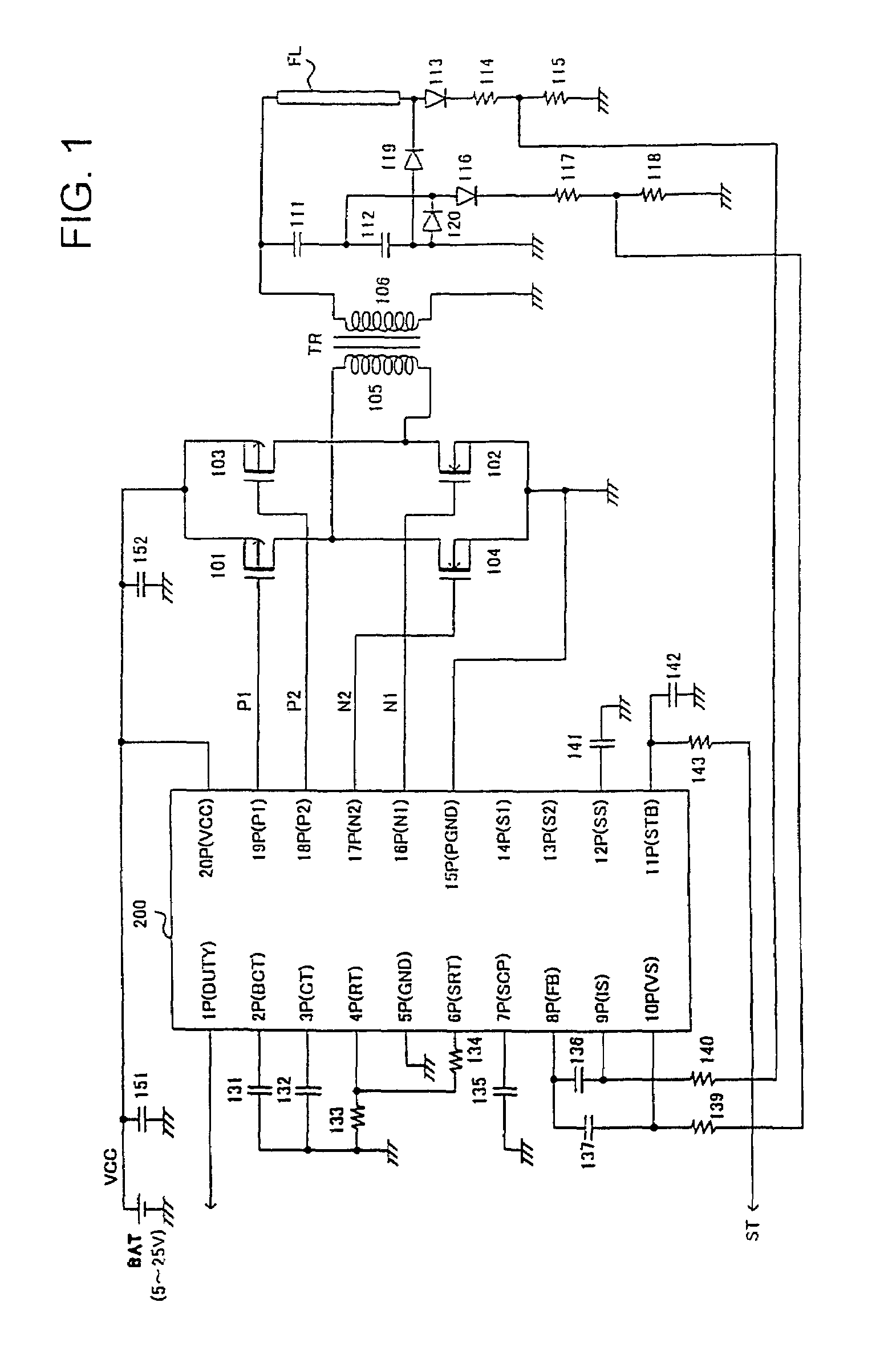
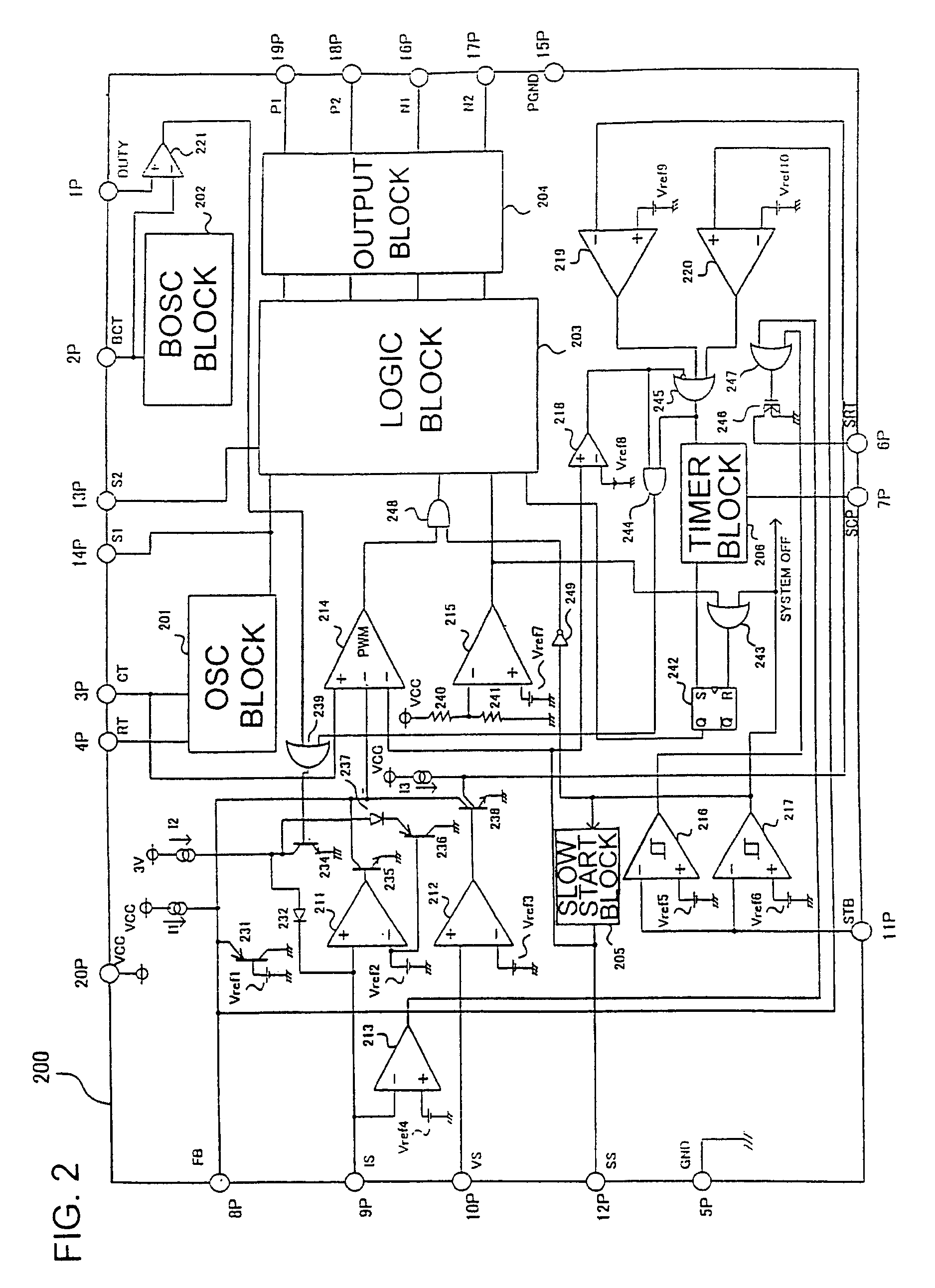
[0095]Referring to FIG. 1, there is shown an overall arrangement of an inverter that includes an insulated transformer TR and a full-bridge (or H-bridge) switch circuit, the inverter adapted to perform PWM control of the intermittent operation of the switch circuit in accordance with the invention. FIG. 2 shows an internal structure of a controller IC 200 for controlling the inverter.
[0096]As shown in FIG. 1, a first switch in the form of a P-type MOSFET (hereinafter referred to as PMOS) 101 and a second switch in the form of an N-type MOSFET (hereinafter referred to as NMOS) 102 together establish a first current path through the primary winding 105 of a transformer TR in a first direction. A third switch in the form of a PMOS 103 and a fourth switch in the form of an NMOS 104 together establish a second current path through the primary winding 105 in a second direction. Each of these PMOSs 101 and 103 and NMOSs 102 and 104 has a body diode (or back gate diode). These body diodes a...
second embodiment
[0170]Referring to FIG. 8, there is shown an overall arrangement of an inverter in accordance with the invention. As shown in FIG. 8, the inverter is provided with two transformers TR1 and TR2 and a half-bridge type switching circuit for performing PWM control. Each of the transformers TR1 and TR2 has two secondary windings 309-310 and 409-410. In the example shown herein, four cold cathode fluorescent lights FL11, FL12, FL21, and FL22 are connected to the second windings 309-310 and 409-410.
[0171]A first transformer system associated with the transformer TR1 of FIG. 8 will be described. This half-bridge type switch circuit has a first capacitor 301 and a first switch in the form of an NMOS 302 that establishes a current path through the primary winding 308 of the transformer TR1 in the first direction (referred to as first path). The switch circuit also has a PMOS 303 serving as a second switch and a second capacitor 304 for establishing a second current path through the primary wi...
PUM
 Abstract
Description
Claims
Application Information
 - R&D
- Intellectual Property
- Life Sciences
- Materials
- Tech Scout
- Unparalleled Data Quality
- Higher Quality Content
- 60% Fewer Hallucinations
Browse by: Latest US Patents, China's latest patents, Technical Efficacy Thesaurus, Application Domain, Technology Topic, Popular Technical Reports.
© 2025 PatSnap. All rights reserved.Legal|Privacy policy|Modern Slavery Act Transparency Statement|Sitemap|About US| Contact US: help@patsnap.com


