
Apparatus and method for electrical and mechanical connection

a technology of electrical and mechanical connection and apparatus, applied in the direction of coupling device connection, coupling device details, contact members penetrating/cutting insulation/cable strands, etc., can solve the problems of difficult mechanical and electrical connection, and achieve the effect of facilitating the transmission of electrical power

Active Publication Date: 2008-12-23
POWER FEED THRU SYST & CONNECTORS
View PDF21 Cites 11 Cited by
  • Summary
  • Abstract
  • Description
  • Claims
  • Application Information

AI Technical Summary

Benefits of technology

"The present invention relates to an apparatus for engaging an electrical conductor, which includes a gripping contact with conical fingers that compress the conductor placed between them. The apparatus also includes a contact receptacle with a conical inner surface that interacts with the conical outer surface of the gripping contact to force the fingers to engage the conductor. The technical effect of this invention is to provide a reliable and efficient way to connect electrical conductors in a wellbore, facilitating the transmission of electrical power to submersible pumps and other equipment."

Problems solved by technology

The size, weight, and orientation of the cables and connectors induce mechanical loads on connector components that make reliable mechanical and electrical connection difficult.
In addition, the physical environment may include high temperature, high pressure, and abrasive and / or corrosive liquids and gases.

Method used


Image

  • Apparatus and method for electrical and mechanical connection
  • Apparatus and method for electrical and mechanical connection
  • Apparatus and method for electrical and mechanical connection

Examples


Embodiment Construction

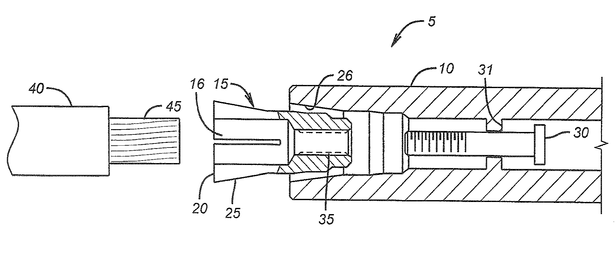
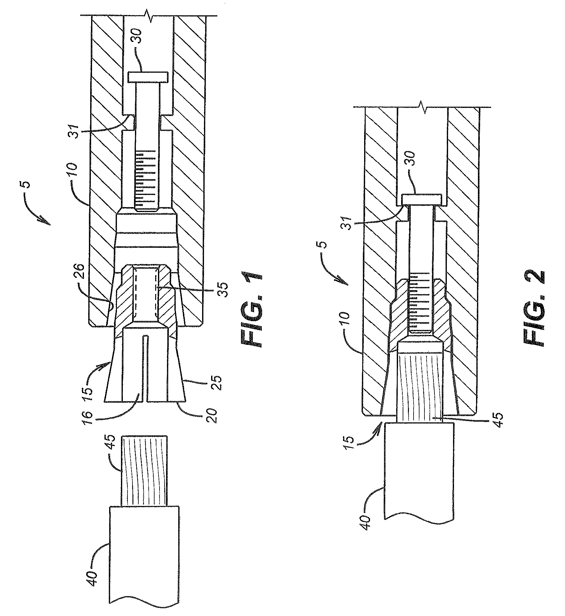
[0018]The following description presents non-limiting examples of embodiments of the present invention. Refer now to FIGS. 1-4B. FIG. 1 shows an exploded view of a connector contact assembly 5 according to one illustrative embodiment of the present invention. As shown in FIG. 1, a cable 40 has an electrical conductor 45 therein. Electrical conductor 45 may be a solid conductor, or, alternatively, a stranded conductor.

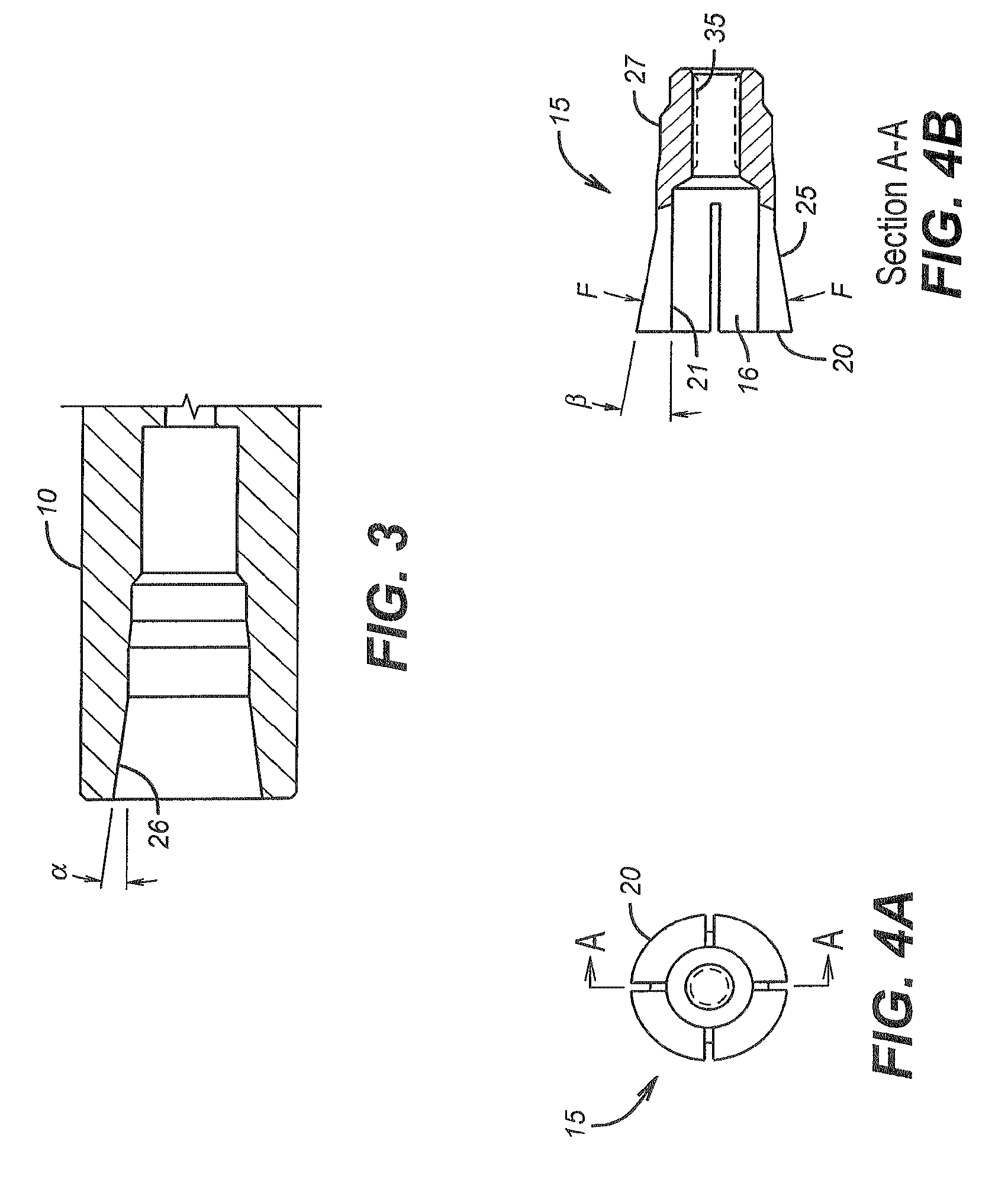
[0019]A gripping contact 15 has a cavity 16 sized to accept electrical conductor 45. In one embodiment, the inner diameter of cavity 16 is a substantially a zero clearance fit with the outer diameter of electrical conductor 45. Gripping contact 15 (see also FIGS. 4A and 4B) comprises a plurality of gripping fingers 20 with an outer surface 25 having a substantially conical shape. As seen, in FIG. 4B, the conical surface 25 is defined by angle β. In one embodiment, angle β is about 6°. Alternatively, angle β may be in the range of about 2° to about 10°. The internal surf...


PUM


Abstract

An apparatus for engaging an electrical conductor comprises a gripping contact having a plurality of fingers, where the plurality of fingers has a substantially conical outer surface. A contact receptacle has a substantially conical inner surface. A tension member urges the gripping contact toward the contact receptacle such that interaction between the substantially conical outer surface and the substantially conical inner surface forces the plurality of fingers to engagingly compress the electrical conductor placed between the fingers. A method of engaging an electrical conductor comprises inserting an electrical conductor between a plurality of fingers of a gripping contact, where the plurality of fingers has a substantially conical outer surface. The substantially conical outer surface of the gripping contact is urged to interact with a substantially conical inner surface of a contact receptacle such that the interaction forces the plurality of fingers to engage the electrical conductor.

Description

CROSS-REFERENCE TO RELATED APPLICATIONS[0001]This application claims priority from U.S. Provisional Application 60 / 812,887 filed on Jun. 12, 2006.BACKGROUND[0002]1. Field of the Invention[0003]The present invention relates to the field of electrical connectors.[0004]2. Background Information[0005]Numerous applications involve the use of electrical connectors. High power connectors are used in applications including subsea connections, and in submersible pump connections in both water wells and oil wells. The size, weight, and orientation of the cables and connectors induce mechanical loads on connector components that make reliable mechanical and electrical connection difficult. In addition, the physical environment may include high temperature, high pressure, and abrasive and / or corrosive liquids and gases.SUMMARY[0006]In one aspect of the present invention, an apparatus for engaging an electrical conductor comprises a gripping contact having a plurality of fingers, where the plura...

Claims


Application Information

Patent Timeline
Patent Type & Authority Patents(United States)
IPC IPC(8): H01R4/38H01R11/09
CPCH01R4/5091H01R4/5025H01R13/5208
Inventor COLESCOTT, MICHAEL G.HORLEY, WAYNEHARVILL, SR., JEFFREY W.JACKSON, ROY
Owner POWER FEED THRU SYST & CONNECTORS
Learn More