
Exhaust gas cleaning apparatus

a technology of exhaust gas and cleaning equipment, which is applied in the direction of lighting and heating equipment, physical/chemical process catalysts, and combustion engines which are operated with fossil fuels. it can solve the problems of inhomogenous regeneration of particulate filters, inability to manufacture conventional particulate filters, and inability to clean exhaust gas channels. it achieves the effect of avoiding local clogging, increasing the stability of material layers, and effective turbulence of exhaust gas

Active Publication Date: 2008-12-23
PUREM GMBH
View PDF44 Cites 11 Cited by
  • Summary
  • Abstract
  • Description
  • Claims
  • Application Information

AI Technical Summary

Benefits of technology

The solution achieves uniform particulate filtration, prevents local clogging, and enhances mechanical stability through turbulent flow and catalytic coating, with a simplified manufacturing process that maintains filter effectiveness and stability.

Problems solved by technology

It is commonly known that combustion engines which are operated with fossil fuels emit pollutants.
It is a disadvantage of the conventional particulate filter that inhomogenous formation of deposits may occur, in particular at the end of exhaust gas channels which are closed at the exit side, and that an inhomogenous temperature profile in the particulate filter may occur, which leads to an inhomogenous regeneration of the particulate filter.
It is a further disadvantage that the manufacturing of a conventional particulate filter, having exhaust gas channels being alternately closed and open, is relatively difficult.

Method used


Image

  • Exhaust gas cleaning apparatus
  • Exhaust gas cleaning apparatus
  • Exhaust gas cleaning apparatus

Examples


second embodiment

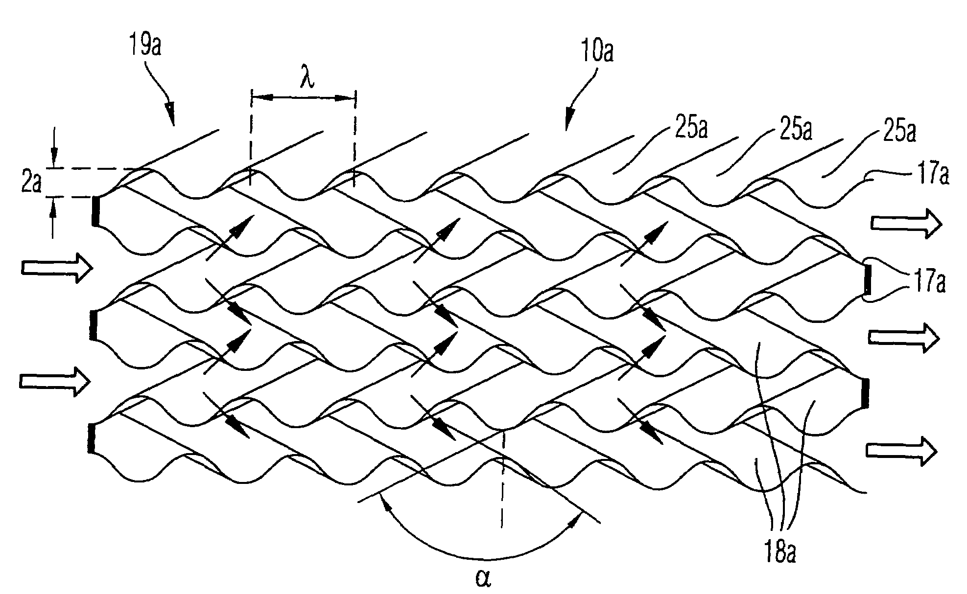
[0083]FIG. 5 shows a perspective longitudinal cross section of a particulate filter 10a, which is the present invention.

[0084]In this embodiment the concave and convex surface areas 25a of the material layers 17a form continuous wave crests and wave troughs which expand substantially linearly. Wave crests and wave troughs of adjacent material layers 17a form an angle α between each other, the angle of which is about 70° in the example shown. A distance λ, i.e. a wave length, between two adjacent wave crests (wave troughs, respectively) is 2 mm, and a maximum deviation 2a of the wave crests and -troughs is 1 mm. By appropriate selection of a ratio of λ and a (relative wave length λ / a) a particular rigidity of the particulate filter structure may be achieved.

[0085]In FIG. 5 the material layers 17a are shown having a distance from each other in a stack 19a. However, the material layers 17a may be on top of each other in order to provide the particulate filter 10a with a particular stab...

third embodiment

[0088]FIG. 7 shows a perspective view of a particulate filter 10b, which is the present invention.

[0089]The webs 29 shown in FIG. 6 are replaced in the particulate filter 10b shown in FIG. 7 by two adjacent material layers 17b of a stack 19b alternately connected to each other at the entry side and the exit side, respectively, by adhering or welding (e.g. seam welding), whereby exhaust gas flow channels 18b are again alternately closed at the entry side and open at the exit side, and open at the entry side and closed at the exit side, respectively.

[0090]It is possible, that the material layers 17b may also be, in addition to adhering, connected to each other by folding, or only by folding. For this, one end of a material layer, which is to be connected to an end of another material layer, is wrapped around the end of the other material layer, and is then clinchingly pressed to the other end.

fourth embodiment

[0091]FIG. 8 shows a perspective view of a particulate filter 10c, which is the present invention.

[0092]Two adjacent material layers 17c of a stack 19c are connected to each other integrally at the entry side and exit side, respectively, in this particulate filter 10c, by means of folding a material sheet.

[0093]FIGS. 9 to 12 show perspective views of particulate filters 10d, 10e, 10f and 10g, which are manufactured in accordance to an inventive method.

[0094]According to the method, a material sheet 17d made of a porous material being permeable to the exhaust gas is folded at fictional folding lines 31 which extend transversely to an extension direction of the material sheet 17d.

[0095]Then, the thus folded material sheet is layered in sections so that a stack 19d is formed. By this layering, exhaust gas flow channels 18d are provided. As in the previous embodiments, these exhaust gas flow channels 18d are alternately closed at the entry side and open at the entry side, and open at t...


PUM

PropertyMeasurementUnit
angleaaaaaaaaaa
distanceaaaaaaaaaa
distanceaaaaaaaaaa

Abstract

An exhaust gas cleaning apparatus for cleaning an exhaust gas emitted from a combustion engine has a stack of plural material layers successively arranged on each other in a stacking direction. The material layers are made of a porous material being permeable to the exhaust gas. The stack has an entry side and an exit side. Plural exhaust gas flow channels are defined in the stacking direction between two adjacent material layers in the stack. The exhaust gas flow channels are defined by surfaces of the material layers which have, when viewed in a flow direction of the exhaust gas from the entry side to the exit side, a plurality of concave and convex areas. A first group of exhaust gas flow channels is formed to be open at the entry side of the stack and closed at the exit side thereof.

Description

BACKGROUND OF THE INVENTION[0001]1. Field of the Invention[0002]The present invention relates to an exhaust gas cleaning apparatus and a method for manufacturing an exhaust gas cleaning apparatus for cleaning an exhaust gas emitted from a combustion engine.[0003]2. Brief Description of Related Art[0004]It is commonly known that combustion engines which are operated with fossil fuels emit pollutants. These pollutants comprise in particular so called particulates, e.g. soot particles, which are harmful to the human organism. As is further known these soot particles are emitted particularly by combustion engines operated with diesel fuel, which may be mainly found in commercial vehicles and increasingly in passenger vehicles.[0005]In order to minimize the amount of these particulates, an exhaust gas cleaning apparatus, i.e. a so called particulate filter, is used, which is arranged in the exhaust gas duct of a combustion engine.[0006]A conventional particulate filter is shown in FIG. 1...

Claims


Application Information

Patent Timeline
Patent Type & Authority Patents(United States)
IPC IPC(8): B01D50/00B01D53/34F01N3/022
CPCF01N3/022F01N3/0226Y10T29/49345F01N2330/14Y02T10/20F01N2330/10Y02T10/12
Inventor GAISER, GERD
Owner PUREM GMBH
Learn More