Method for mounting a radiator in a radio device and a radio device

a radiator and radio technology, applied in the structural form of radiating elements, resonant antennas, protective materials, etc., can solve the problems of deteriorating electrical properties, and achieve the effect of stabilizing the electric properties of antennas, low production costs, and relatively cheap raw materials

Inactive Publication Date: 2008-12-23
PULSE FINLAND
View PDF11 Cites 52 Cited by
  • Summary
  • Abstract
  • Description
  • Claims
  • Application Information

AI Technical Summary

Benefits of technology

[0009]The invention has an advantage that the radiator of the antenna of the radio device becomes fastened to the radio device very firmly, which has a stabilizing effect on the electric properties of the antenna. The invention further has an advantage that the antenna can be formed using relatively cheap raw materials. The antenna has relatively low production costs in other respects, too. Furthermore, the invention has the advantage that it is well suited for manufacturing an antenna that utilizes the inner space of the radio device efficiently.

Problems solved by technology

When the mobile stations become smaller, even with regard to thickness, the distance mentioned above is inevitably reduced, whereby the electric properties deteriorate.

Method used


Image

  • Method for mounting a radiator in a radio device and a radio device
  • Method for mounting a radiator in a radio device and a radio device
  • Method for mounting a radiator in a radio device and a radio device

Examples


Embodiment Construction

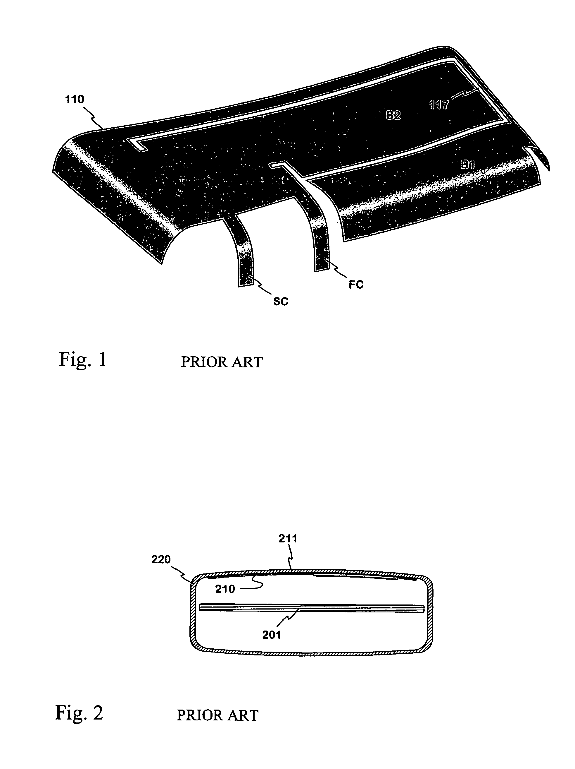
[0019]FIGS. 1 and 2 were already discussed in connection with the description of the prior art.

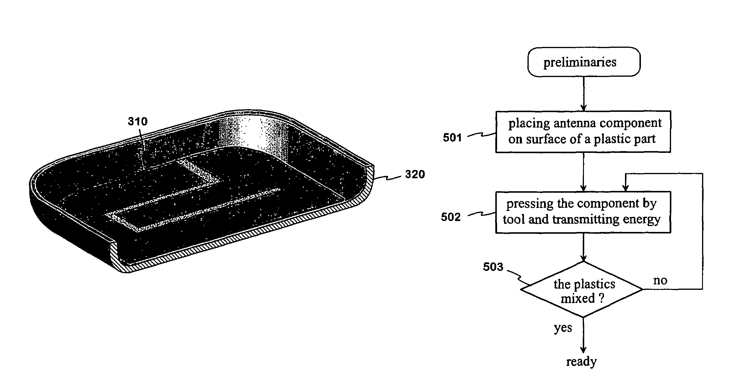
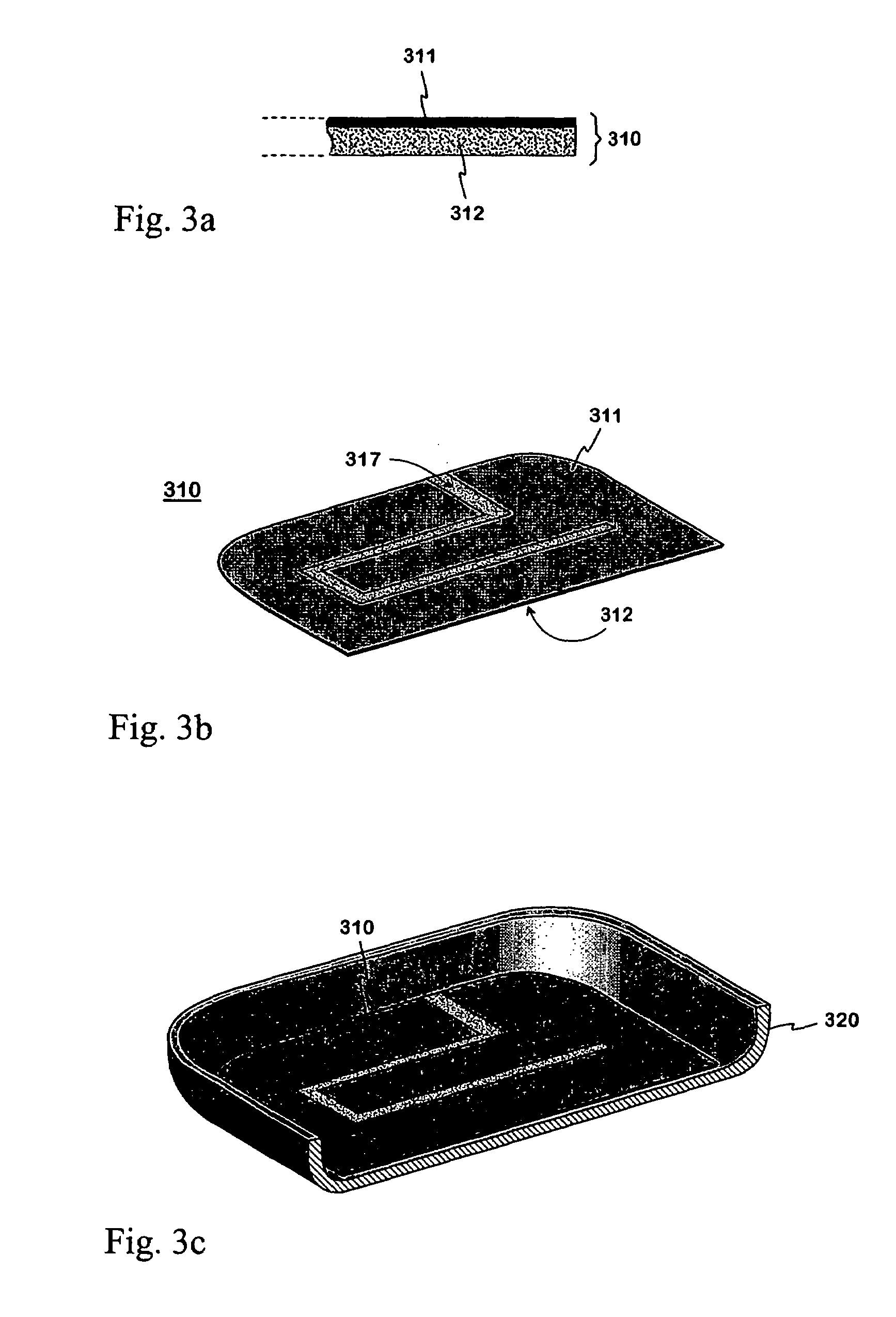
[0020]FIGS. 3a, 3b and 3c show an example of an antenna component according to the invention and its location. FIG. 3a presents an enlarged cross-section of the antenna component. The antenna component 310 comprises a planar radiator 311 and a layer 312 made of thermoplastic dielectric material. The radiator 311 and the layer 312 are on top of each other and join firmly to each other for the whole of their area. FIG. 3b shows the antenna component 310 as a perspective drawing. As viewed from above, it is shaped like a rectangle with two corners rounded to correspond to the shape of the end of a small-sized radio device. In this example, the radiator 311 has a non-conductive slot 317 starting from its edge. The slot is shaped so that the radiator is divided into two branches of different lengths, as viewed from the short-circuit point of the antenna, to be located beside the open end of the...


PUM


Abstract

The invention relates to a method for mounting a radiating antenna element used especially in the manufacture of small-sized radio devices and a radio device with a radiator mounted by the method. A thin thermoplastic plate coated with a metal foil is used in the manufacture of the antenna. A radiator pattern is formed in the metal foil. The antenna component obtained is placed (401) on the surface of some plastic part of the radio device, preferably on the inner surface of the thermoplastic cover of the radio device. The plastic layer of the antenna component becomes positioned against said plastic part, and the component is fastened (402, 403) by fusing together the mating plastic materials, which are against each other. In the complete antenna, the radiator is electrically connected to the other parts of the radio device by means of contacts. The radiator of the antenna of the radio device becomes fastened to the radio device very firmly, which has a stabilizing effect on the electric properties of the antenna. In addition, the antenna can be formed using relatively cheap raw materials.

Description

CROSS-REFERENCE TO RELATED APPLICATION[0001]The present application is a continuation of International Patent Application Serial No. PCT / FI2004 / 000507, filed Sep. 2, 2004, published in English, which claims priority to Finnish Patent Application No. 20031298, filed Sep. 11, 2003, both of which are hereby expressly incorporated by reference in their entireties.TECHNICAL FIELD[0002]The invention relates to a method for mounting a radiating antenna element, i.e. a radiator, used especially in the manufacture of small-sized radio devices. The invention also relates to a radio device which has a radiator manufactured by the method.BACKGROUND OF THE INVENTION[0003]The invention is used to form an antenna that does not change the appearance of the radio device. In small-sized radio devices, such as mobile stations, such antennas usually have a planar structure: The antenna comprises a planar radiating element and a ground plane parallel with it. The electric properties of the planar antenn...

Claims


Application Information

Patent Timeline
Patent Type & Authority Patents(United States)
IPC IPC(8): H01Q1/40H01Q1/24H01Q1/38H01Q9/04
CPCH01Q1/243H01Q1/38H01Q9/0421H01Q9/0442
Inventor NIEMI, MATTIANTILA, KIMMONIEMELA, ILKKA
Owner PULSE FINLAND
Why Eureka
Try Eureka