Inkjet recording head

a recording head and inkjet technology, applied in the field of inkjet recording heads, can solve the problems of inability to form, inability to meet the needs of printing, and inability to meet the needs of printing, and achieve the effects of high densification, high densification of nozzles, and high resolution and miniaturization

Inactive Publication Date: 2008-12-30
FUJIFILM BUSINESS INNOVATION CORP
View PDF8 Cites 7 Cited by
  • Summary
  • Abstract
  • Description
  • Claims
  • Application Information

AI Technical Summary

Benefits of technology

[0013]In light of the above problems, the present invention provides an inkjet recording head where high densification of the nozzles and the formation of minute pitch interconnects (wiring) required for the high densification of the nozzles are both realized so that high resolution and miniaturization are achieved.

Problems solved by technology

However, any of the above-described cases, interconnects arrangement in which a pitch between each wire is minute (e.g., 10 μm pitch or less) cannot be formed.
Thus, there are problems in that when the nozzle density rises, the sizes of the mounting substrate and the FPC inevitably become large, miniaturization is inhibited and costs increase.
Moreover, there is the problem that when the nozzle density rises, interconnects having a desired resistance cannot be installed as desired.
In other words, there is a limit on increasing the nozzle density resulting from the restriction of the interconnects density.

Method used


Image

  • Inkjet recording head
  • Inkjet recording head
  • Inkjet recording head

Examples


Embodiment Construction

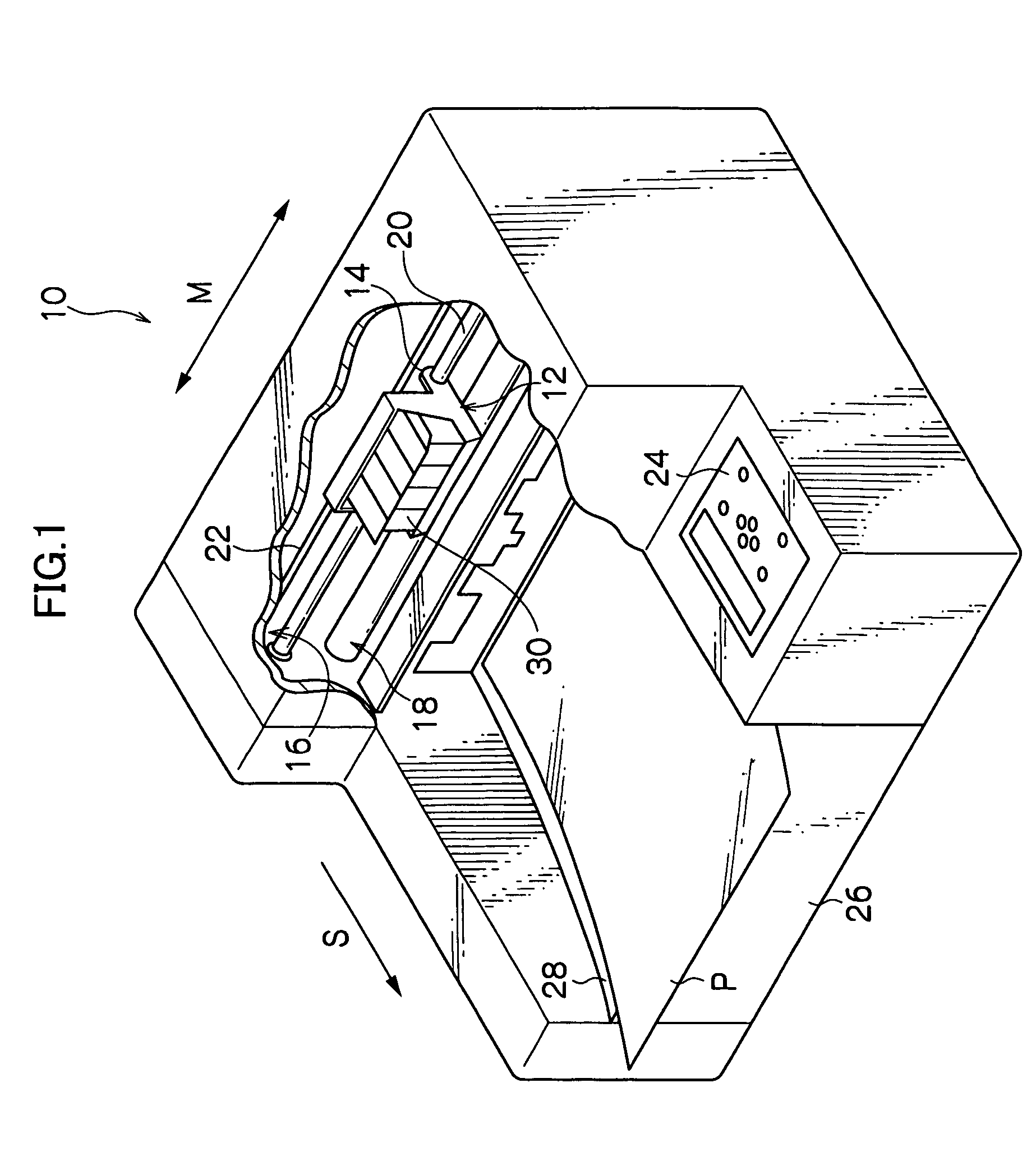
[0050]Embodiments of the invention will be described in detail below on the basis of examples shown in the drawings. Explanation will be conducted using recording paper P as a recording medium. Also, the conveyance direction of the recording paper P in an inkjet recording device 10 will be represented by arrow S as a sub-scanning direction, and the direction orthogonal to the conveyance direction will be represented by arrow M as a main scanning direction. Also, where an arrow UP and an arrow LO are shown in the drawings, the arrow UP will represent an upper direction and the arrow LO will represent a lower direction. When expressions indicating up and down are given, these will correspond to the aforementioned arrows.

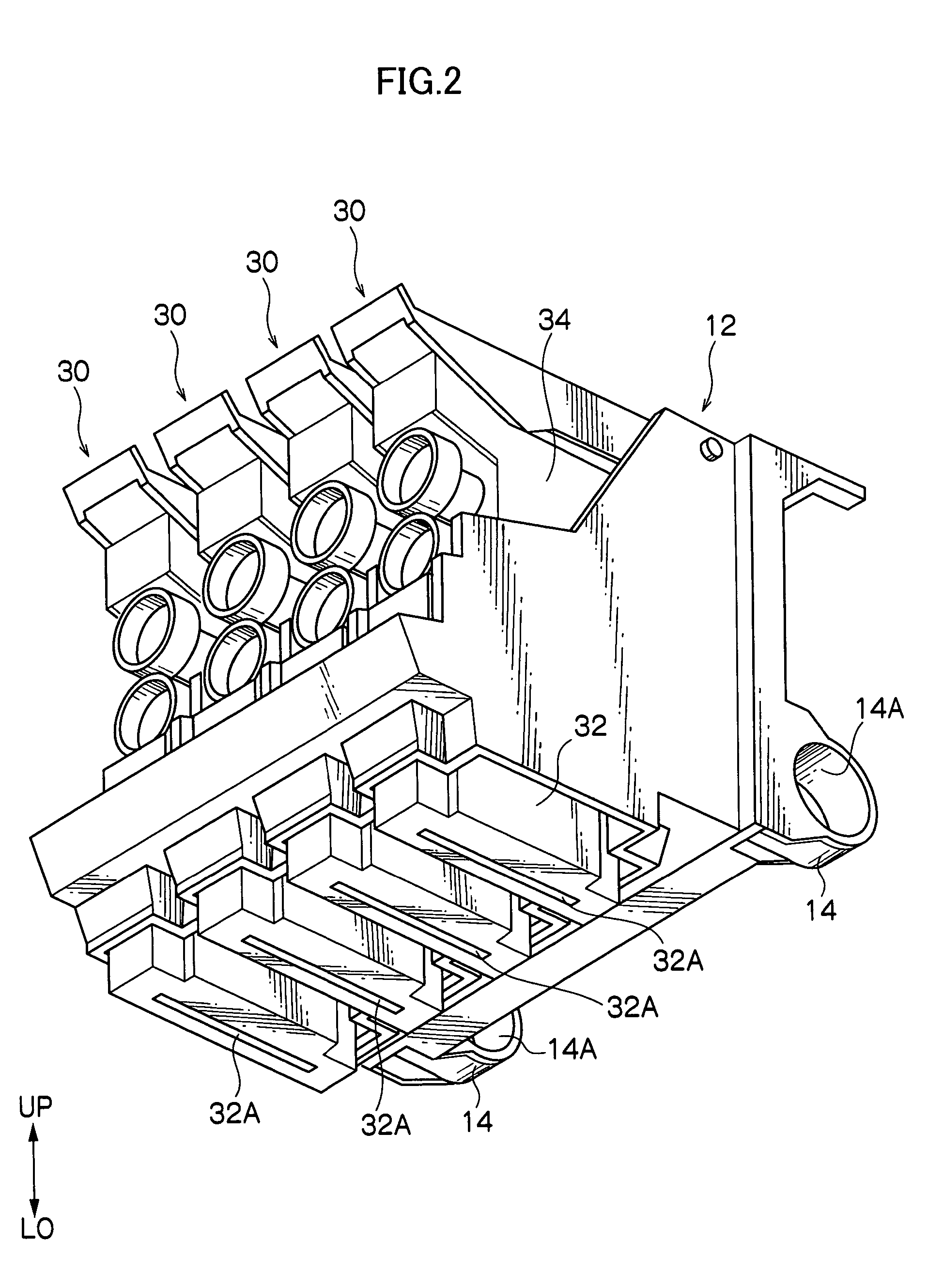
[0051]First, the overview of the inkjet recording device 10 will be described. As shown in FIG. 1, the inkjet recording device 10 is disposed with a carriage 12 in which are loaded inkjet recording units 30 (inkjet recording heads 32) of black, yellow, magenta and cyan...


PUM


Abstract

An inkjet recording head includes: nozzles that jet ink droplets; pressure chambers that communicate with the nozzles and contain ink; a diaphragm that configures part of the pressure chambers; an ink pool chamber that pools ink to be supplied to the pressure chambers via ink flow paths; and piezoelectric elements that cause the diaphragm to be displaced, wherein the ink pool chamber is disposed opposite from the pressure chambers with the diaphragm being disposed therebetween, and drive ICs that apply a voltage to the piezoelectric elements are mounted on a piezoelectric element substrate formed to include the diaphragm.

Description

CROSS-REFERENCE TO RELATED APPLICATION[0001]This application claims priority under 35 USC 119 from Japanese Patent Application No. 2004-173169, the disclosure of which is incorporated by reference herein.BACKGROUND OF THE INVENTION[0002]1. Field of the Invention[0003]The present invention relates to an inkjet recording head including nozzles that jet ink droplets, a pressure chamber that communicates with the nozzles and contains ink, a diaphragm that configures part of the pressure chamber, an ink pool chamber that pools ink to be supplied to the pressure chamber via an ink droplet path, and a piezoelectric element that displaces the diaphragm.[0004]2. Description of the Related Art[0005]Conventionally, inkjet recording devices are known where ink droplets are selectively discharged from plural nozzles of an inkjet recording head (sometimes referred to simply as “recording head” hereinafter) that reciprocally moves in a main scanning direction, and where characters and images are p...

Claims


Application Information

Patent Timeline
Patent Type & Authority Patents(United States)
IPC IPC(8): B41J2/14B41J2/045B41J2/04B41J2/055B41J2/16
CPCB41J2/14233B41J2/161B41J2/1623B41J2/1628B41J2/1629B41J2/1631B41J2/1632B41J2/1642B41J2/1643B41J2/1646B41J2002/14241B41J2002/14419B41J2002/14459B41J2002/14491B41J2202/18
Inventor MURATA, MICHIAKIUSAMI, HIROYUKIINOUE, NANAO
Owner FUJIFILM BUSINESS INNOVATION CORP
Why Eureka
Try Eureka