Tibia component and sliding plate of a knee-joint endoprosthesis

a technology of tibia and endoprosthesis, which is applied in the field of tibia components, can solve the problems of premature implant loosening, high shearing force and torsional stress of fixed sliding components, and achieve the effect of reducing rotational force and number of tibial plateau components

Inactive Publication Date: 2008-12-30
PETER BREHM HLDG GMBH & CO KG
View PDF10 Cites 3 Cited by
  • Summary
  • Abstract
  • Description
  • Claims
  • Application Information

AI Technical Summary

Benefits of technology

[0008]It is an object of the invention to embody a modular concept which enables polyethylene sliding plates on which a femoral component rests that are compatible with one another and have varying degrees of mobility to be placed on one and the same tibial plateau so that the number of tibial plateau components that must be kept available in the operating room can be reduced substantially. Moreover, use is intended to be made of the advantage of highly mating congruency in shape of the femoral and sliding component on which it rests, however accompanied with a reduction of the rotational forces that occur in this combination.

Problems solved by technology

Shaping the bi-condylar femoral and sliding component on which the femoral component rests must allow for the fact that highly congruent medial and lateral articulation surfaces will reduce the pressure load on polyethylene by offering an enlarged bearing area, but may restrict the degrees of freedom of the natural sliding-rolling motion of the joint of axial tibial rotation, this leading to high shearing forces and torsional stresses in a fixed sliding component.
Undesired consequences consist in premature implant loosening in addition to high local strain, deformation and wear of the polyethylene sliding component.

Method used


Image

  • Tibia component and sliding plate of a knee-joint endoprosthesis
  • Tibia component and sliding plate of a knee-joint endoprosthesis
  • Tibia component and sliding plate of a knee-joint endoprosthesis

Examples


Embodiment Construction

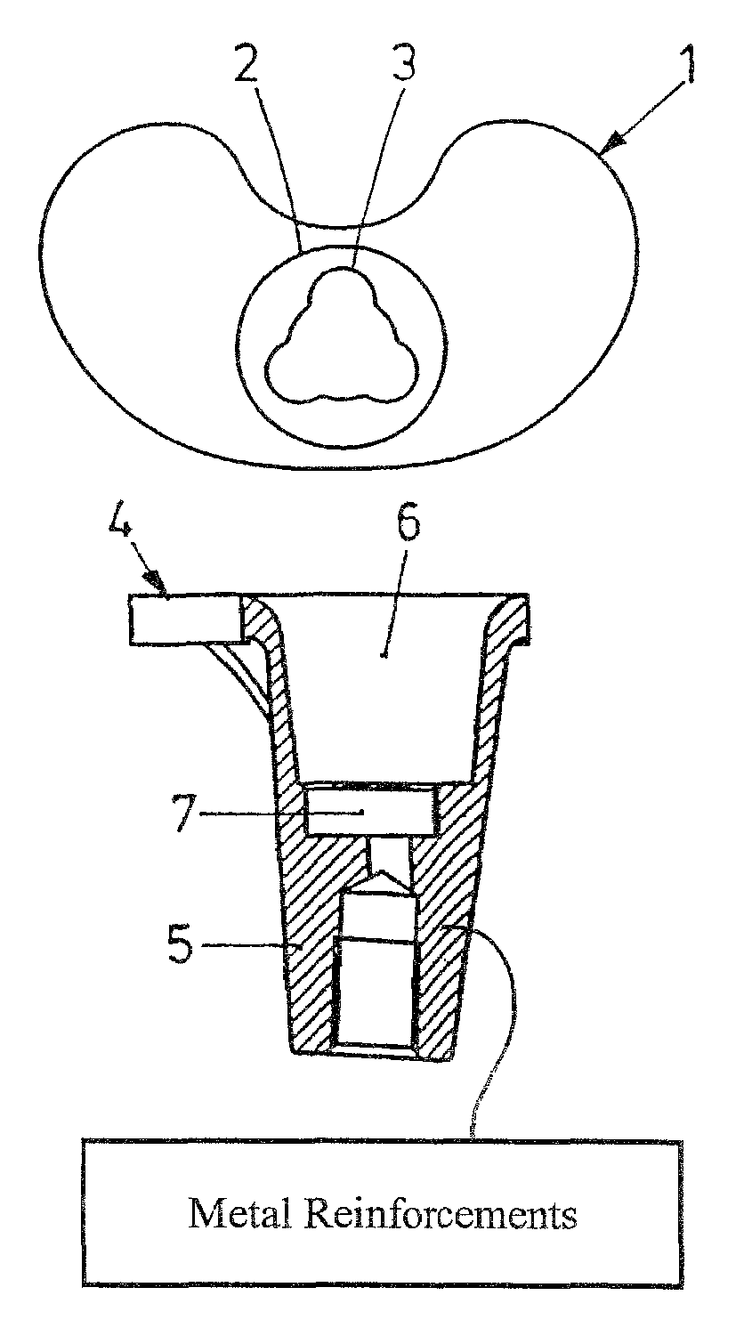
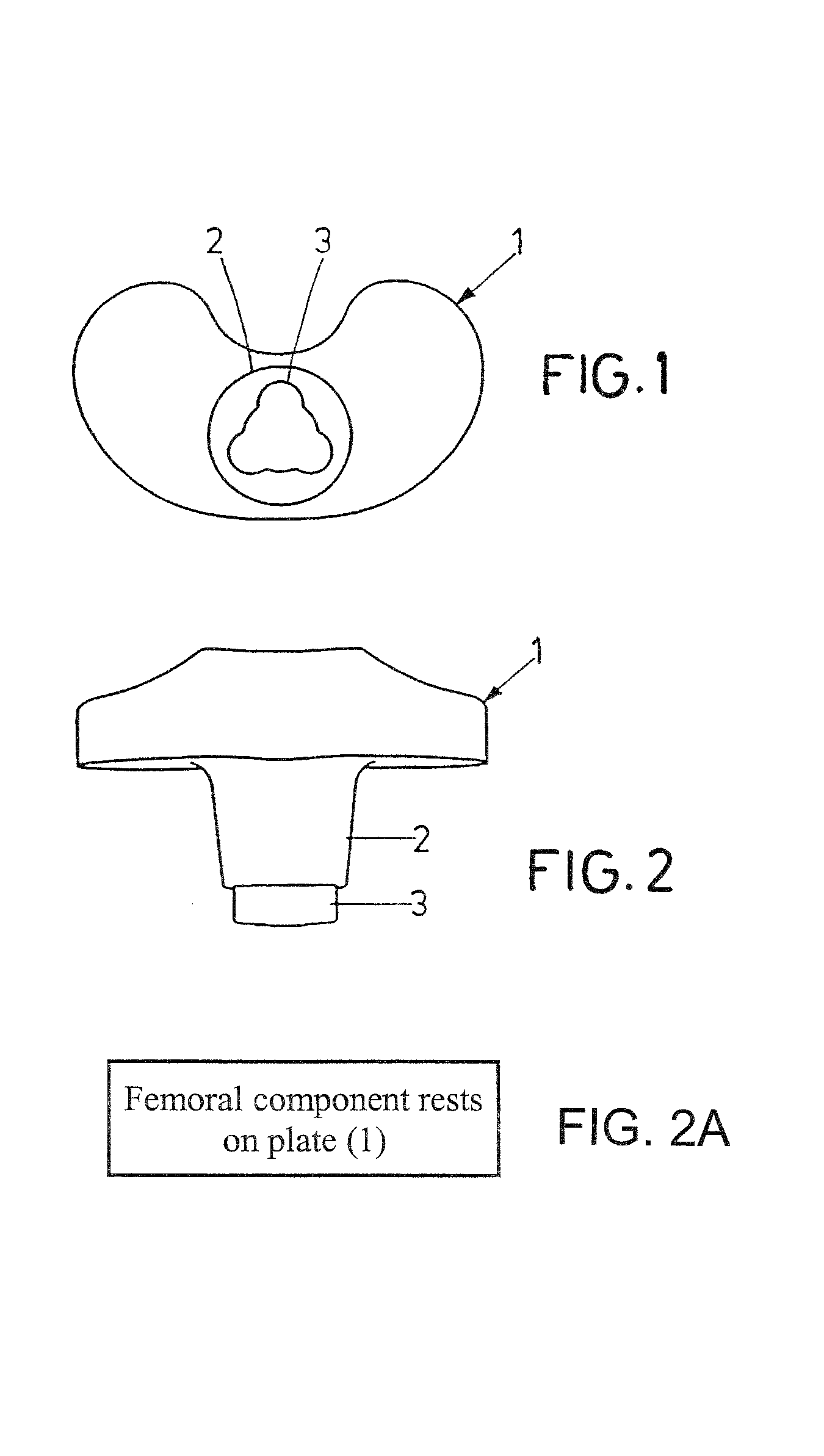
[0028]A sliding plate 1 of polyethylene seen in FIGS. 1 and 2 has a reniform basic shape, with an attachment 2 extending downwards which has an end portion 3 of triangular basic shape with rounded corners as seen in FIG. 1.

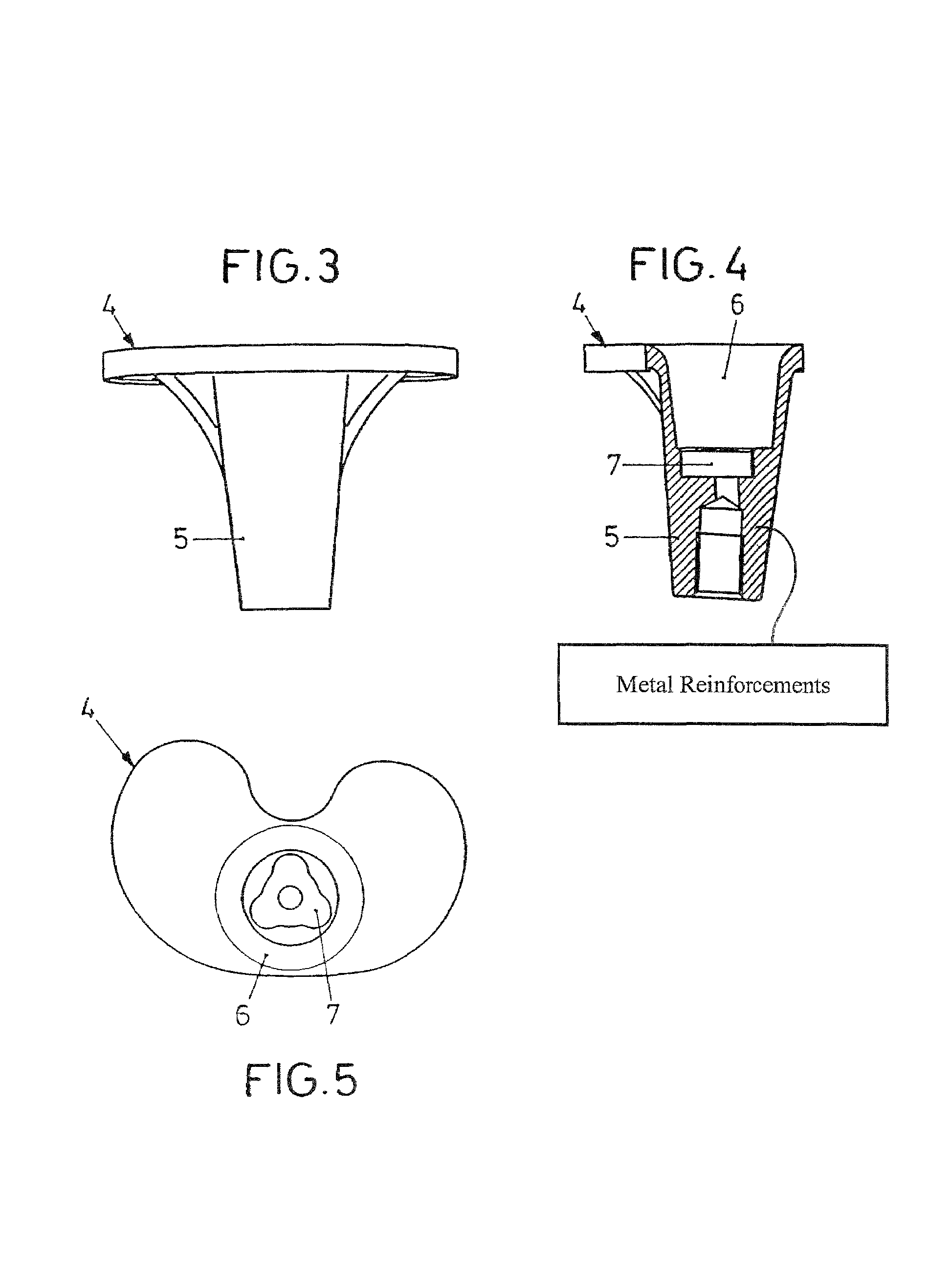
[0029]The tray 4 seen in FIGS. 3 to 5 is equipped with an anchor portion 5 which extends downwards, having an recess 6 that mates the shape of the attachment 2 of the sliding plate 1.

[0030]The bottom side of the recess 6 is provided with a recess 7 of smaller diameter which has a triangular basic shape with rounded corners and an outer contour that corresponds to the outer contour of the end portion 3.

[0031]When the sliding plate 1 seen in FIGS. 1 and 2 is inserted by its attachment 2 first into the recess 6, the end portion 3 engages with the recess 7 by positive fit so that a non-rotatable connection is produced.

[0032]Correspondingly it is possible to apply sliding plates 1 of varying degrees of mobility, using one and the same tibial plateau component 4.


PUM

PropertyMeasurementUnit
molecular weightaaaaaaaaaa
shapeaaaaaaaaaa
degrees of freedomaaaaaaaaaa

Abstract

In a tibial component comprising an anchor portion for being fixed in bone and a tray for a sliding plate of polyethylene, the tibial component cooperating with a femoral component which rests on the sliding plate by curved articulation surfaces, it is provided that the sliding plate (1) has an attachment (2) which extends inside the anchor portion (5) of the tibial plateau component (4) and which, distally of the tibial plateau component, is non-rotatably joined to the anchor portion (5) by positive fit.

Description

BACKGROUND OF THE INVENTION[0001]1. Technical Field of the Invention[0002]The invention relates to a tibial component which comprises an anchor portion for being fixed in bone; and to a tray for a sliding plate of polyethylene, the tibial component cooperating with a femoral component which rests on the sliding plate by curved articulation surfaces.[0003]2. Prior Art[0004]A knee joint endoprosthesis of the generic type has been described for example in P 41 02 509 A1.[0005]Fundamentally, it is the object of a knee joint replacement to re-establish the function of the joint as far as possible by an endoprosthesis. In doing so, special consideration must be reserved for the kinematics and biomechanics involved and their principle of sliding-rolling motions. A knee joint prosthesis must be able to copy such motions and to absorb the strain by flexion, extension and rotation without any damages to the bone bearing and capsular ligament system.[0006]To this end, endoprostheses have been ...

Claims


Application Information

Patent Timeline
Patent Type & Authority Patents(United States)
IPC IPC(8): A61F2/38A61F2/00A61L27/00A61F2/30
CPCA61F2/3868A61F2/30965A61F2002/30112A61F2002/30133A61F2002/30136A61F2002/30156A61F2002/30332A61F2002/30367A61F2002/30377A61F2002/30574A61F2002/30604A61F2002/30616A61F2002/3079A61F2002/30792A61F2002/30878A61F2002/30884A61F2220/0033A61F2230/0004A61F2230/0015A61F2230/0023
Inventor BREHM, PETER
Owner PETER BREHM HLDG GMBH & CO KG
Why Eureka
Try Eureka