Advanced low voltage lighting system

a lighting system and low-voltage technology, applied in the field of electric arts, can solve the problems of high circuit current, waste of present system, slow technological evolution, etc., and achieve the effect of increasing the pleasure of viewers and improving the utilization of conductor capacity

Inactive Publication Date: 2008-12-30
AVATAR SYST
View PDF5 Cites 60 Cited by
  • Summary
  • Abstract
  • Description
  • Claims
  • Application Information

AI Technical Summary

Benefits of technology

[0010]Now in accordance with the present invention, there have been found systems and methods which provide low voltage lighting s

Problems solved by technology

Despite the success of low voltage lighting systems in the marketplace, their technological evolution has been slow.
First is that the present system is wasteful.
Utilization of an AC power source in low voltage power circuits results in high circuit currents.
This problem frequently cannot be cured by simply raising the source voltage.
The result is that conductors within a circuit that have the capacity to carry the required power are nevertheless unable to do so when a voltage limitation is imposed.
The common solution is that larger conductors are used and valuable resources are wasted.
The second reason to seek out improvements over the traditional technology is that installers have problems installing these systems.
Because high currents fl

Method used


Image

  • Advanced low voltage lighting system
  • Advanced low voltage lighting system
  • Advanced low voltage lighting system

Examples


embodiment 200

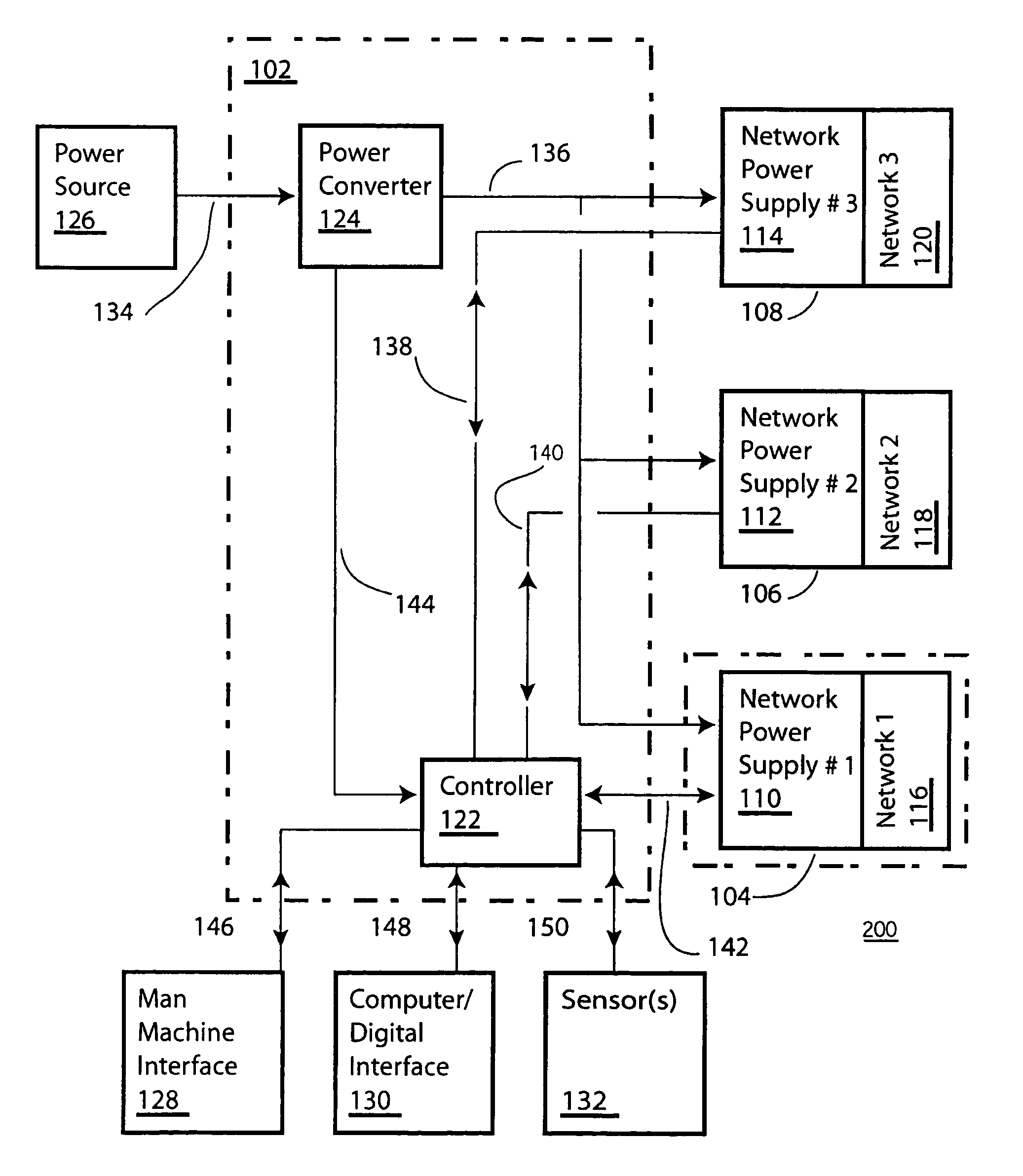
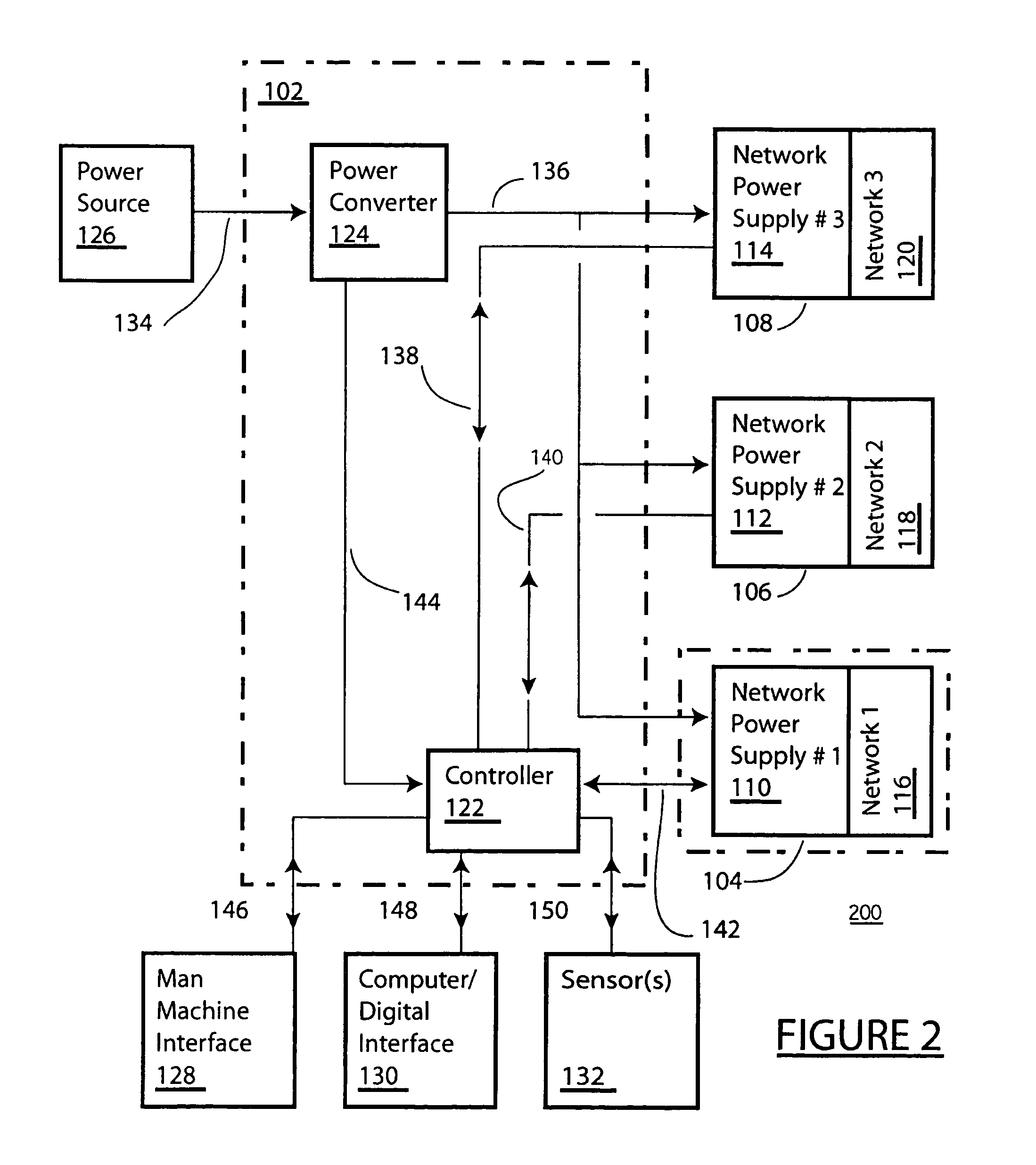
[0040]FIG. 2 shows an embodiment 200 of the lighting system 100. Here, the power, interface, and the control block 102 includes a power converter 124, a controller 122, and a plurality of circuits for making interconnections. A first power circuit 134 supplies power from a power source 126 to the power converter. A second power circuit 144 supplies power from the power converter to the controller. A third power circuit 136 interconnects respective first, second, and third network power supplies 110, 112, 114 with the power converter. First, second, and third bidirectional signal circuits 142, 140, 138 interconnect respective first, second, and third network power supplies 110, 112, 114 with the controller. Fourth, fifth, and sixth bidirectional signal circuits 146, 148, 150 interconnect respectively a man machine interface 128, a computer / digital interface 130, and sensor(s) 132 with the controller.

[0041]In some embodiments, the controller includes multiple controllers or control el...

embodiment 300

[0044]FIG. 3 shows an embodiment 300 of the first lighting subsystem 104. The first lighting subsystem 104 includes the first load network 120 and the first network power supply 110. Included in the first load network is a first trunk circuit 306 and a first load 302. First trunk circuit 306 couples a power output 304 of the first network power supply 110 and a power input 308 of the load 302. In an embodiment, the load 302 includes a plurality of discrete loads powered from the power input of the load network. In some embodiments a plurality of trunk circuits may be included, each trunk circuit supplying a respective power input of a respective load.

[0045]FIG. 4 shows another embodiment 400 of the first lighting subsystem 104. The first lighting subsystem 104 includes the first load network 116 and the first network power supply 110. Included in the first load network is a first trunk circuit 306 and a first load distribution network 409. The first trunk circuit coules the power ou...

embodiment 800

[0057]FIG. 8 shows an embodiment 800 of the controller 122. Here, the controller includes a bus 853 interconnecting memory, timers 862 and input / output interfaces. Memory includes program memory 868, volatile RAM memory 866, and non-volatile memory 864. Input / output interfaces include a local operator interface 854, interface to external input / output 856, analog to digital converter for sensor input / output 858, and power switch drivers 860 for driving external devices. As a person of ordinary skill in the art will understand, one or more of each of these devices may be incorporated into a single controller and / or replicated where elements of the controller are replicated to realize and / or support a plurality of functions or external input / output. One or more of these devices may be implemented in a single component or in multiple interconnected components. An example of a suitable hardware controller is the PIC18F8720 microcontroller available from Microchip Technology Incorporated ...


PUM


Abstract

Disclosed is a lighting system supporting multiple independently controlled zones utilizing a plurality of semiconductor switches coupled to a plurality of transformers to produce a non-sinusoidal power output and controlled by a digital controller that receives feedback from each zone in order to auto-sense the proper voltage for a plurality of connected loads.

Description

CROSS REFERENCE TO RELATED APPLICATIONS[0001]This application claims the benefit of and incorporates by reference U.S. Provisional Application 60 / 613,008 filed Sep. 24, 2004 and entitled ADVANCED EXTERIOR LIGHTING SYSTEM.BACKGROUND OF THE INVENTION[0002]1. Field of the Invention[0003]The present invention pertains to the electrical arts. More particularly, the present invention pertains to systems and methods for providing a low voltage lighting system.[0004]2. Description of the Related Art[0005]Low voltage incandescent lighting systems are well known in this country. Typical applications include indoor specialty, task and feature lighting and outdoor landscape lighting. Since Edison's invention of the “Electric-Lamp” and Tesla's pioneering work on transformers in the 1880's, the technology required to build similar low voltage lighting systems has been available. Mass production and more recently the proliferation of low cost manufacturers overseas have placed low voltage lighting...

Claims


Application Information

Patent Timeline
IPC IPC(8): G05F1/00
CPCH05B37/0254H05B37/0263H05B37/029H05B47/155H05B47/18H05B47/185
Inventor WACKNOV, JOELBRUMBAUGH, RANDALL W.CHANCELLOR, PAUL D.KELLER, KENNETH W.MCSHANE, DAVID J.
Owner AVATAR SYST
Why Eureka
Try Eureka