Start control apparatus for internal combustion engine

a technology of internal combustion engine and control apparatus, which is applied in the direction of engine starters, electric control, instruments, etc., can solve the problems of increasing vibration, and achieve the effect of effectively restrainting the generation of compression self-ignition, and reducing the risk of vibration

Inactive Publication Date: 2008-12-30
TOYOTA JIDOSHA KK +1
View PDF17 Cites 20 Cited by
  • Summary
  • Abstract
  • Description
  • Claims
  • Application Information

AI Technical Summary

Benefits of technology

[0004]Here, one of objects of the present invention is to provide a start control apparatus for an internal combustion engine capable of restraining self-ignition at starting in a cylinder in which the piston stops in an intake stroke.
[0006]According to the start control apparatus of the first aspect, more fuel is injected to the cylinder in which the piston starts its operation from the intake stroke when starting the internal combustion engine than the fuel injection amount for other cylinders. Accordingly, cylinder temperature drop effect due to fuel vaporization latent heat is higher in comparison with those in other cylinders, and the generation of the self-ignition is restrained by maintaining lower cylinder temperature even if the compression stroke starts under the state that cylinder pressure increases due to suction of air during stopping. Therefore, the problems such as increase of vibration accompanying the self-ignition can be restrained, thereby starting the internal combustion smoothly.
[0008]According to the start control apparatus of the second aspect, distinguishing whether or not the position of the piston stopping in the intake stroke is within the predetermined crank angle range from the start position of the intake stroke allows to appropriately control the fuel injection amount for the cylinder in which the piston starts its operation from the intake stroke. For example, between an initial stage and a mid stage of the intake stroke, a remaining intake time is long, intake flow rate and velocity are high fuel, so that intake air can sufficiently be mixed with each other, and intake temperature is lower than the cylinder temperature. Therefore, the cylinder temperature drop effect due to vaporization latent heat is effectively exerted. In such a case, the fuel injection amount is increased to restrain the generation of the self-ignition. On the other hand, in a final stage of the intake stroke, the remaining intake time is short and the intake flow rate and velocity are reduced, so that the fuel amount necessary to reduce the cylinder temperature using the vaporization latent heat is rapidly increased. Therefore, it is difficult to provide the cylinder temperature drop effect appropriate for the increase of the fuel. In such a case, the fuel injection amount is relatively reduced to thereby restrain problems such as deterioration of a fuel consumption and emission.
[0009]In one embodiment of the start control apparatus according to the second aspect, when the position of the piston stopping in the intake stroke is within the predetermined crank angle range, the fuel injection amount control device may increase the fuel injection amount at starting for the cylinder in which the piston stops in the intake stroke more than a fuel injection amount for other cylinders. Alternatively, when the position of the piston stopping in the intake stroke is within the predetermined crank angle range, the fuel injection amount control device may increase the fuel injection amount at starting for the cylinder in which the piston stops in the intake stroke more than in the case of exceeding the predetermined crank angle range. According to these embodiments, the cylinder temperature drop effect by the vaporization latent heat can certainly and effectively be exerted by increasing the fuel amount in a predetermined range from the start of the intake stroke.
[0013]Also, in one embodiment of the start control apparatus according to the first or second aspect, the fuel injection amount control device may control the fuel injection amount for a cylinder distinguished that the piston position at the stop of the internal combustion engine is in the intake stroke so that an air fuel ratio in the cylinder becomes lean relative to a theoretical air fuel ratio with respect to an air quantity in the cylinder. In this case, the air fuel ratio in the cylinder in which the piston stops in the intake stroke is more lean than stoichiometry, and therefore the pressure increase in the cylinder when starting the internal combustion engine can be restrained, and the rising thereof would not be rapid. Therefore, although the output torque may be small, the sound and vibration can be restrained. Furthermore, injecting excessive fuel is not required, and therefore the discharge of carbon dioxide (HC) can be minimized.
[0014]As explained above, according to the present invention, by increasing the fuel injection amount for the cylinder subject to starting of the piston from the intake stroke, the cylinder temperature can be reduced as using the vaporization latent heat of the fuel, and the self-ignition in the compression stroke can effectively be restrained. Also, by controlling the fuel injection amount in consideration of the stop position of the piston, the self-ignition restrain effect can effectively be exerted more, while the problems such as deteriorations of the fuel consumption and emission can be restrained.

Problems solved by technology

The self-ignition causes problems such as increasing vibration.
Also, the above-described self-ignition problem is not limited to the cylinder direct injection type internal combustion engine but may occur in the so-called port injection type internal combustion engine.
Furthermore, the self-ignition problem is not limited to the case of restarting from the idle stop state, but may occur in the case that the internal combustion engine restarts prior to sufficient reduction of the cylinder temperature after the internal combustion engine stops in response to an action of turning the ignition switch off.

Method used


Image

  • Start control apparatus for internal combustion engine
  • Start control apparatus for internal combustion engine
  • Start control apparatus for internal combustion engine

Examples


Embodiment Construction

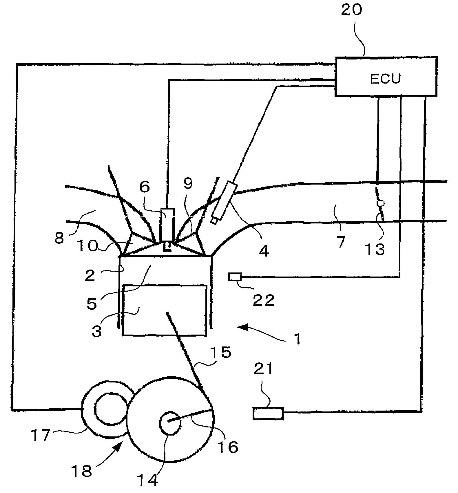
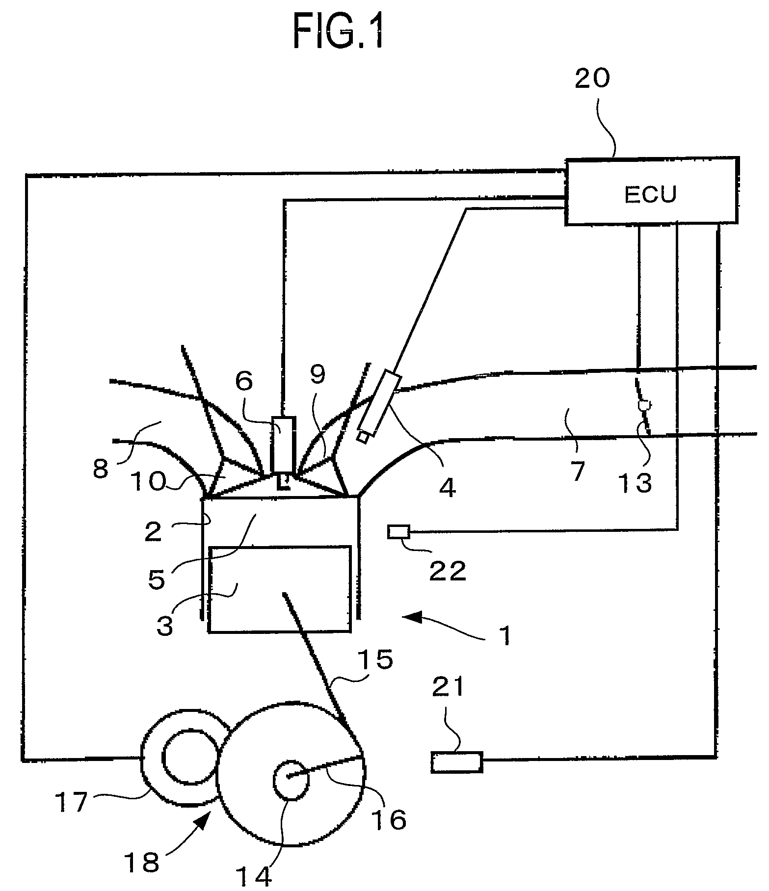
[0025]FIG. 1 is a view showing an internal combustion engine for an automobile to which a start control apparatus according to one embodiment of the present invention is applied. In FIG. 1, the internal combustion engine (hereinafter referred to as an engine) 1 is constructed as, for example, a 4-cycle engine and includes plural cylinders 2. Incidentally, FIG. 1 only shows a single cylinder 2 but structures of remaining cylinders 2 are the identical thereto.

[0026]The phase of a piston 3 in each cylinder 2 is displaced from each other in correspondence to the number and the layout of the cylinders 2. For example, in a straight four cylinder engine with four of cylinders 2 arranged in one direction, the phase of the piston 3 is displaced 180 degrees in the crank angel from each other. Therefore, one of four cylinders 2 is inevitably in the intake stroke. Furthermore, the engine 1 is constructed as a port injection type engine which injects fuel from a fuel-injection valve 4 to an inta...


PUM


Abstract

There is provided a start control apparatus for an internal combustion engine (1) which starts the engine with injecting fuel to each cylinder (2) of the internal combustion engine in an intake stroke. The apparatus comprises a stop position distinction device (20) which distinguishes a piston position at a time of a stop of the internal combustion engine, and a fuel injection amount control device (20) which specifies a cylinder in which a piston stops in the intake stroke based on a distinction result of the stop position distinction device and which increases a fuel injection amount at starting for the specified cylinder more than a fuel injection amount for other cylinders.

Description

TECHNICAL FIELD[0001]The present invention relates to an apparatus that controls a fuel amount to be injected to a cylinder of an internal combustion engine at starting.BACKGROUND ART[0002]As a start control apparatus for a cylinder direct injection type internal combustion engine which is subjected to idle stop control, there is known a start control apparatus in which, when fuel feed pressure during an idle stop state goes below a predetermined pressure, fuel is injected to each of a cylinder in which a piston stops in a compression stroke and a cylinder in which a piston stops in an intake stroke and then performs an intake stroke injection at restarting, thereby promptly starting the engine (see, for example, Japanese Patent Application Laid-Open (JP-A) No. 2004-36561). In addition, JP-A Nos. 2001-73774, 2000-213385, and 2202-242724 are other publications with related arts to the present invention.[0003]In case that the internal combustion engine stops due to the idle stop contr...

Claims


Application Information

Patent Timeline
Patent Type & Authority Patents(United States)
IPC IPC(8): F02D45/00
CPCF02D41/065F02D35/02F02D41/008F02D41/009F02D2041/0095F02D2041/0092F02N11/08
Inventor TAKEYAMA, MASAKINAKAMURA, MAKOTOKATO, MINORUKUROKI, RENTARO
Owner TOYOTA JIDOSHA KK
Why Eureka
Try Eureka