Mass customization configurator

a configurator and customization technology, applied in the field of automatic configuration of electronics enclosures, can solve the problems of time-consuming and labor-intensive current methods for configuring enclosures, and consequently high cost, and achieve the effect of accelerating the time-to-market for a customized enclosure assembly and reducing the engineering life cycl

Inactive Publication Date: 2008-12-30
TELLABS BEDFORD
View PDF4 Cites 66 Cited by
  • Summary
  • Abstract
  • Description
  • Claims
  • Application Information

AI Technical Summary

Benefits of technology

[0005]The present invention provides an system and method for automated configuration of electronics enclosures. The system typically receives requirements in the form of an initial design and generates a completed design including placement schedule, power usage schedules and heat flow schedules. The system may be adapted to optimize arrangement and selection of components according to customer requirements. The customer requirements are typically communicated to the system using an interactive question-and-answer interface. Included as output of the system is a bill of materials (“BOM”), an equipment layout drawing and pricing based on predetermined material and labor pricing. The system can greatly accelerate the time-to-market for a customized enclosure assembly by reducing the engineering life cycle from days to minutes.

Problems solved by technology

Systems available for assisting rack configuration merely provide component placement assistance and do not account for requirements drive by functionality, device interoperability or environmental conditions within the rack.
Thus, current methods for configuring enclosures tend to be time-consuming and labor-intensive and consequently expensive.

Method used


Image

  • Mass customization configurator
  • Mass customization configurator
  • Mass customization configurator

Examples


Embodiment Construction

[0012]Embodiments of the present invention will now be described in detail with reference to the drawings, which are provided as illustrative examples so as to enable those skilled in the art to practice the invention. Notably, the figures and examples below are not meant to limit the scope of the present invention. Where certain elements of these embodiments can be partially or fully implemented using known components, only those portions of such known components that are necessary for an understanding of the present invention will be described, and detailed descriptions of other portions of such known components will be omitted so as not to obscure the invention. Further, the present invention encompasses present and future known equivalents to the components referred to herein by way of illustration.

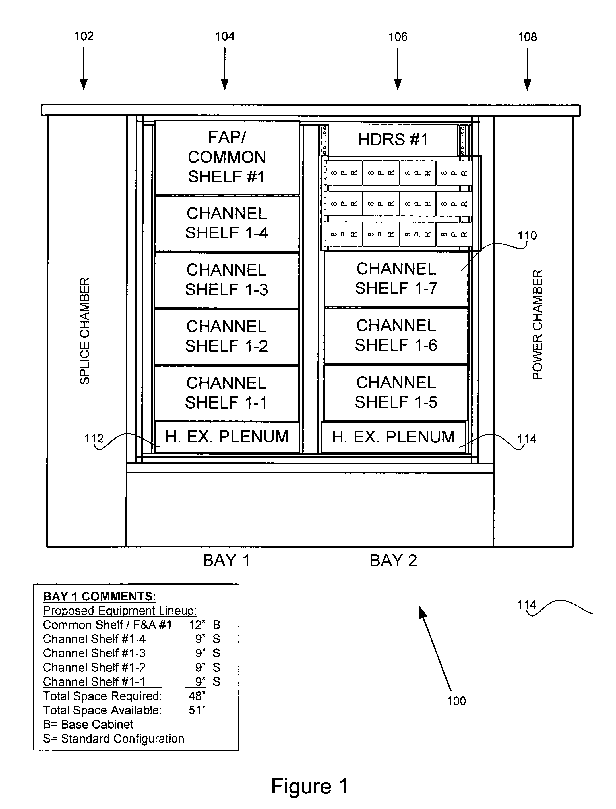
[0013]The following discussion describes the process for configuring enclosures using an example of a telecommunications rack such as that depicted generally at 100 in FIG. 1. In the ...


PUM


Abstract

The present invention provides an automated configuration system and method for electronics enclosures. The system receives user requirements generates a configuration including placement schedule, power usage schedules and heat flow schedules. Included as output of the system is a bill of materials, an equipment layout drawing and pricing based on predetermined material and labor pricing. Methods for generating a configuration are described that include iteratively repeating combinations of the steps of generating design rules, deriving a placement schedule, mapping the distribution of power usage within the enclosure and producing a heat flow analysis. Processes used to generate the configuration can be controlled by design rules derived from user requirements.

Description

BACKGROUND OF THE INVENTION[0001]1. Field of the Invention[0002]The present invention relates to automated configuration of electronics enclosures. The present invention more particularly relates to computer-based systems for configuring enclosures housing telecommunications racks.[0003]2. Description of Related Art[0004]Currently, electronics enclosures such as telecommunications racks are manually configured to meet requirements set by a customer. Systems available for assisting rack configuration merely provide component placement assistance and do not account for requirements drive by functionality, device interoperability or environmental conditions within the rack. However, electronics enclosures must be configured with various electronic sub-racks according to engineering rules for placement of equipment, cooling capability, modules based on traffic loading, vendor equipment preference, and power storage requirements. Additionally, telecommunication service providers (custome...

Claims


Application Information

Patent Timeline
Patent Type & Authority Patents(United States)
IPC IPC(8): G06F17/50
CPCG06F17/5072G06F17/5081G06F30/392G06F30/398
Inventor LOW, ANDREW G.CRYSTAL, FRANZ T.
Owner TELLABS BEDFORD
Why Eureka
Try Eureka