Hydraulic differential for integrated drive generator

a technology of drive generator and hydraulic differential, which is applied in the direction of fluid couplings, gearings, couplings, etc., can solve the problems of port plate needing to be machined to impractical tolerances, end-to-end arrangement tending to generate high hydraulic thrust forces between the interfaces, etc., to achieve reasonable manufacturing tolerances in the porting method

Inactive Publication Date: 2009-01-06
HAMILTON SUNDSTRAND CORP
View PDF8 Cites 30 Cited by
  • Summary
  • Abstract
  • Description
  • Claims
  • Application Information

AI Technical Summary

Benefits of technology

[0005]The invention comprises a hydraulic differential that has radial dynamic porting between the variable and fixed displacement hydraulic units to avoid large hydraulic thrust forces between them and allows for reasonable manufacturing tolerances in the porting method.
[0006]Generally, the invention comprises a hydraulic differential with a variable displacement hydraulic unit of the axial piston type, a fixed displacement hydraulic unit of the axial piston type, a stationary housing for mounting the hydraulic units, an input shaft for coupling to a variable speed power source and an output shaft for coupling to a constant speed load, comprising: a wobbler and a port plate for the variable displacement hydraulic unit coupled to the stationary housing; an axial block and piston set for the variable displacement hydraulic unit, a port plate for the fixed displacement hydraulic unit and a wobbler for the fixed displacement hydraulic unit coupled to the input shaft; and an axial block and piston set for the fixed displacement hydraulic unit coupled to the output shaft; wherein the variable displacement hydraulic unit port plate and the fixed displacement hydraulic unit port plate couple together through a circumferential interface to minimise hydraulic thrust forces developed by the hydraulic units.

Problems solved by technology

However, such an end-to-end arrangement also tends to generate high hydraulic thrust forces between the interfaces of the hydraulic units since they generate significant working pressure in operation.
Consequently, the hydraulic differential requires large bearings to withstand these hydraulic thrust forces, adding to cost, weight and size of the hydraulic differential.
One disadvantage is that the variable and fixed port plates needs to be shimmed close together to minimize leakage between the variable and fixed blocks port plates or the piece parts that clamp around the port plate need to be machined to impractical tolerances.

Method used


Image

  • Hydraulic differential for integrated drive generator
  • Hydraulic differential for integrated drive generator
  • Hydraulic differential for integrated drive generator

Examples


Embodiment Construction

[0012]A hydraulic differential that is suitable for incorporating the invention comprises a variable and fixed axial piston machine combination. This combination works to maintain a constant output rotational speed for a predetermined input rotational speed range. In this way, it converts a variable speed power source, such as an engine, to a constant speed that is suitable for powering a constant speed device, such as a fixed frequency alternating current generator.

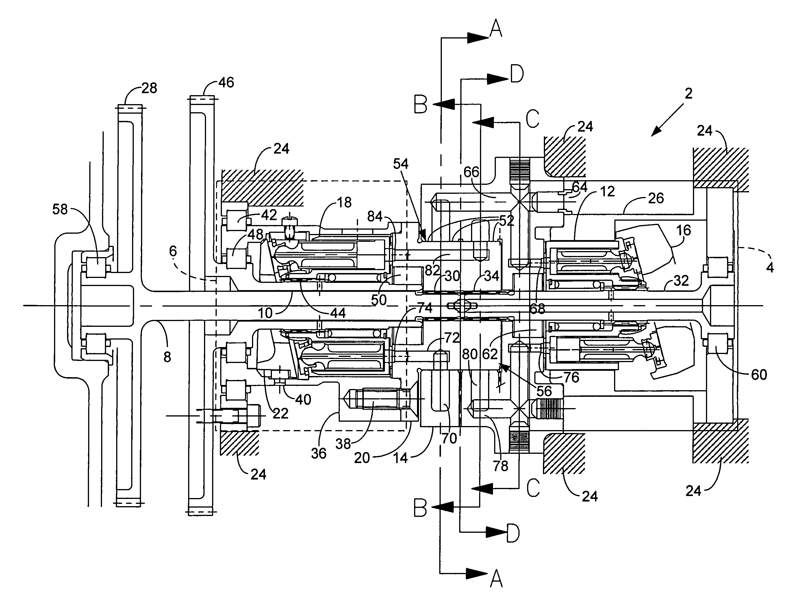
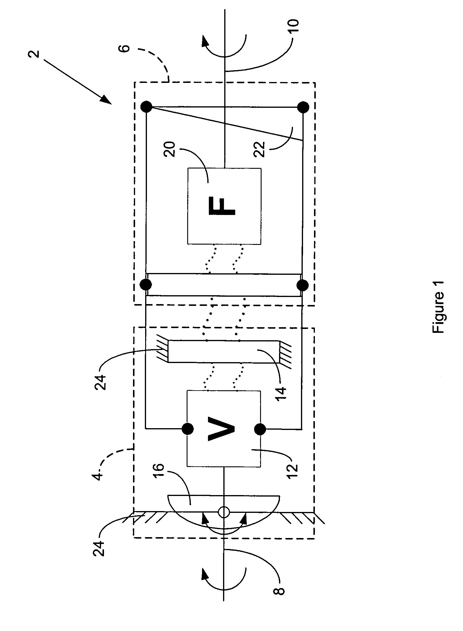
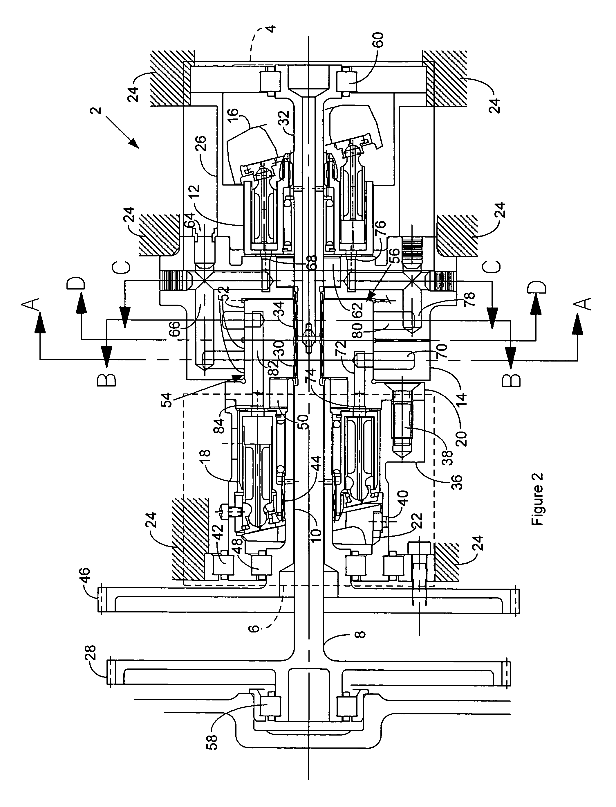
[0013]FIG. 1 is a block diagram of a hydraulic differential 2 that is suitable for incorporating the invention. The hydraulic differential 2 comprises a variable displacement hydraulic unit 4, a fixed displacement hydraulic unit 6, an input power shaft 8 and an output power shaft 10. The variable displacement hydraulic unit 4 comprises a variable unit block and piston set 12, a variable unit port plate 14 and a variable unit wobbler 16. The fixed displacement hydraulic unit 6 comprises a fixed unit block and piston set 1...


PUM


Abstract

A hydraulic differential with a variable displacement hydraulic unit of the axial piston type, a fixed displacement hydraulic unit of the axial piston type, a stationary housing for mounting the hydraulic units, an input shaft for coupling to a variable speed power source and an output shaft for coupling to a constant speed load, comprises: a wobbler and a port plate for the variable displacement hydraulic unit coupled to the stationary housing; an axial block and piston set for the variable displacement hydraulic unit, a port plate for the fixed displacement hydraulic unit and a wobbler for the fixed displacement hydraulic unit coupled to the input shaft; and an axial block and piston set for the fixed displacement hydraulic unit coupled to the output shaft; wherein the variable displacement hydraulic unit port plate and the fixed displacement hydraulic unit port plate couple together through a circumferential interface to minimise hydraulic thrust forces developed by the hydraulic unit.

Description

FIELD OF THE INVENTION[0001]The invention relates to a hydraulic differential, and more particularly to a hydraulic differential that eliminates high hydraulic thrust loads that act on bearings or housing structure.BACKGROUND OF THE INVENTION[0002]A common type of hydraulic differential comprises a first axial piston hydraulic machine of variable displacement coupled to a second axial piston hydraulic machine of fixed displacement in such a fashion that driving one of the hydraulic machines at a certain rotational speed with a source of mechanical power whilst changing the phase and amplitude of displacement of the variable displacement machine relative to its porting causes a change in rotational speed of the undriven hydraulic machine. This operation is particularly useful for converting a source of mechanical power that has a variable rotational speed to a constant rotational speed. By changing the displacement of the variable hydraulic machine in proportion to the mechanical sou...

Claims


Application Information

Patent Timeline
Patent Type & Authority Patents(United States)
IPC IPC(8): F16H39/10F16H61/48
CPCF16H39/14F16H39/10
Inventor GROSSKOPF, ANDREW PKANDIL, MAGDY ALEMMERS, GLENN C.BEHLING, DAVID S.
Owner HAMILTON SUNDSTRAND CORP
Why Eureka
Try Eureka