Air cleaner

a technology for air cleaners and air cleaners, applied in the field of air cleaners, can solve the problems of adverse influence, welding residue, and unsuitable general use of absorbers, and achieve the effect of reducing radiation noise and reducing quality and performance of air cleaners

Inactive Publication Date: 2009-01-06
TOYO ROKI MFG CO LTD
View PDF7 Cites 10 Cited by
  • Summary
  • Abstract
  • Description
  • Claims
  • Application Information

AI Technical Summary

Benefits of technology

[0011]The present invention has been conceived in consideration of the circumstances mentioned above and an object of the present invention is to provide an air cleaner provided with an adsorption element capable of reducing a radiation noise without reducing quality and performance of the air cleaner.
[0017]According to the air cleaner of present invention of the aspects mentioned above, since the adsorption element is mounted along the inner surface of the air cleaner housing, air passing resistance of the air passing the inside of the air cleaner can be prevented from increasing and, moreover, the air flow is not disturbed, thus effectively adsorbing carbon or like contained in the air.
[0019]In addition, the formation of the ribs extending laterally and transversely so as to intersect each other can effectively prevent the generation of radiant noise.
[0020]In the first aspect of the present invention, the first fusing projection is surrounded by the ribs at the oscillation fusing process, so that burrs generated inside the housing can be prevented by the ribs from scattering.
[0021]In the second aspect of the present invention, the ribs can attain the silencing function to the radiant noise, and the scattering of the burr can be prevented by the formation of the wall sections to the attachment portion, thus protecting the burr from entering into the engine.
[0022]Since the adsorption element is disposed in the clean side of the housing, the gasified fuel from the engine can be preliminarily adsorbed by the adsorption element to thereby prevent the gasified fuel from entering into the dirty side.

Problems solved by technology

However, in the air cleaner disclosed in the publication 1, it is obliged to manufacture the adsorbing member specifically for such air-cleaner, and accordingly, the adsorbing member is not suitable for the general use.
On the other hand, in the air cleaner disclosed in the publication 2, at the time of attaching the adsorption element, it may be adversely influenced with heat for heating the pin.
In addition, at the heating time of the pin, there may exist a fear of generation of welding residue from a front end of the fused pin, and moreover, in the air cleaner shown in this publication 2, since the adsorption element covers the whole air passage, air passing resistance will be increased, thus being inconvenient.

Method used


Image

  • Air cleaner
  • Air cleaner
  • Air cleaner

Examples


first embodiment

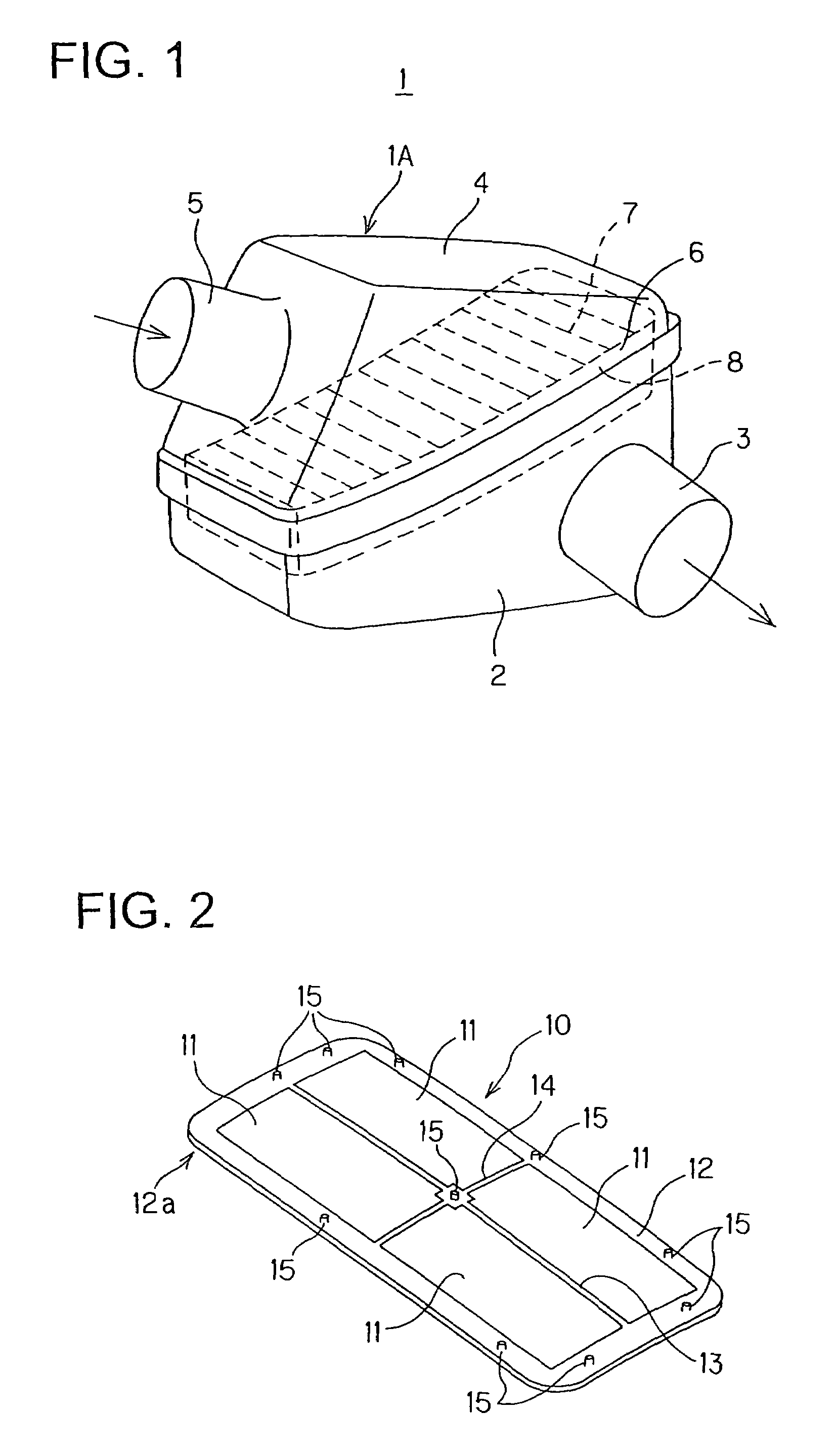
[0033]the present invention will be described hereunder with reference to FIGS. 1 to 4, in which terms “upper”, “lower”, “right”, “left” and the like terms are used with reference to the illustration of the drawings or in a generally usable state of an air cleaner.

[0034]An air cleaner 1 of this embodiment has a housing 1A provided with a case 2 having an upper surface opened and a cover 4 having a lower surface opened, the opened lower surface of the cover 4 being placed on the opened upper surface of the case 2 to thereby constitute the housing 1A.

[0035]The air cleaner 1 also has a filter element 6 disposed inside the housing 1A in a manner such that the filter element 6 is sandwiched between the upper surface of the case 2 and the lower surface of the cover 4. This filter element 6 is composed of a pleated filter (filtrating) member 7 and a frame member 8 surrounding the outer peripheral edge of the filter member 7 so as to support it. As not shown in detail in FIG. 1, a packing i...

second embodiment

[0054]the present invention will be described hereunder with reference to FIGS. 7 and 8.

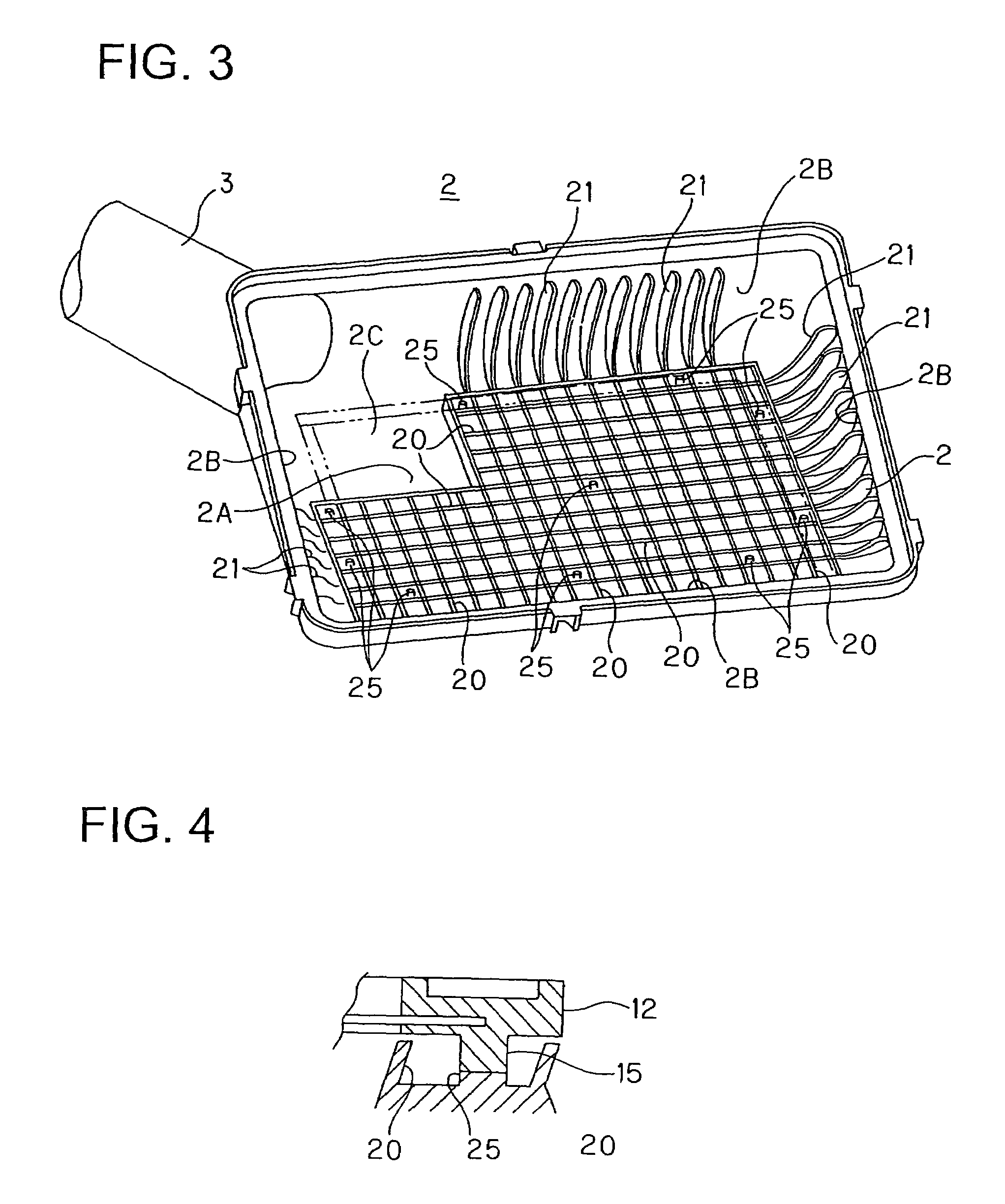
[0055]In the air cleaner 1 shown in FIG. 7, the rear surface of the frame 12 of the adsorption element 10 is entirely oscillation-fused to the inner surface of the case 2. The case 2 of the air cleaner 1 of this second embodiment has a basic structure substantially the same as that of the case 2 of the air cleaner 1 of the first embodiment, so that like reference numerals are added to elements or portions corresponding to those in the first embodiment and description thereof will be omitted herein.

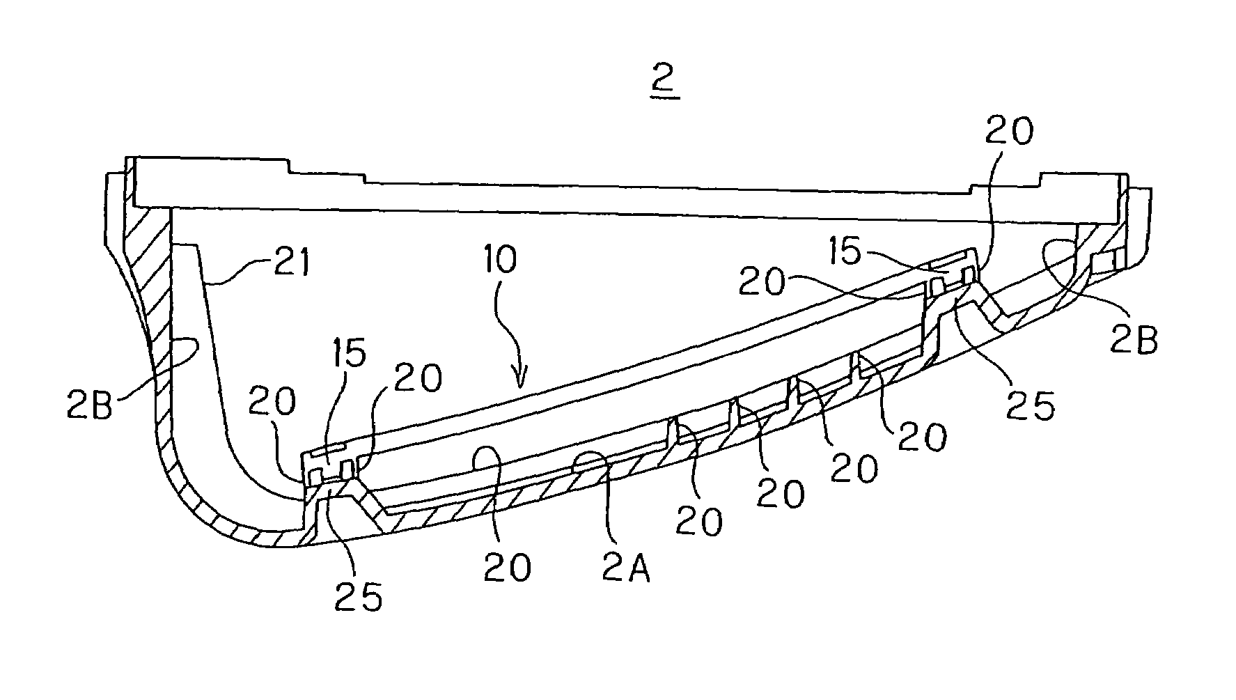
[0056]In the case 2 of this embodiment, a plurality of ribs 20 extending laterally and transversely are formed to the inner surface of the bottom surface portion 2A so as to project thereform. A rectangular area 2C at which no rib is formed is formed near the exhaust port 3. Further, in the area at which the ribs are formed, an attachment portion 30 having a predetermined width is mounted in a rectangul...


PUM

PropertyMeasurementUnit
areaaaaaaaaaaa
adsorptionaaaaaaaaaa
air passing resistanceaaaaaaaaaa

Abstract

An air cleaner is provided with a housing, a filter element disposed inside the housing for filtrating air introduced into the housing, and an adsorption element disposed in the housing for adsorbing gasified fuel in the housing, the adsorption element including an adsorbing member adsorbing gasified fuel and a frame surrounding the adsorbing member to hold the adsorbing member. The air cleaner further includes a plurality of first fusing projections projecting from one surface of the frame, a plurality of ribs formed to an inner surface of the housing so as to project therefrom and extending laterally and transversely to cross each other, and a plurality of second fusing projections formed to the inner surface of the housing at positions corresponding to the location of the first fusing projections formed to the frame of the adsorption element, each of the second projections being surrounded by a pair of crossing ribs.

Description

BACKGROUND OF THE INVENTION[0001]1. Field of the Invention[0002]The present invention relates to an air cleaner for filtrating an air flowing in an intake system of an internal combustion engine.[0003]2. Related Art[0004]In an internal combustion engine, there may cause such a case as that an evaporated and gasified fuel flows inside an air cleaner from an engine side. In a conventional art, in order to adsorb such gasified air, an adsorbing member (or adsorbent) is disposed in the air cleaner in addition to a filter element.[0005]For example, in an air cleaner disclosed in Japanese Patent Unexamined Application (KOKAI) Publication No. 2001-336454, a plurality of ribs are formed, so as to extend in parallel, to an inner surface of a housing of the air cleaner, and the adsorbing member is disposed between these ribs.[0006]Furthermore, an air cleaner disclosed in Japanese Patent Unexamined Application (KOKAI) Publication No. 2002-266731 is provided with a filter element so as to divid...

Claims


Application Information

Patent Timeline
Patent Type & Authority Patents(United States)
IPC IPC(8): F02M35/02B01D53/02
CPCB01D46/0036B01D46/10B01D46/521F02M35/024B01D2277/20
Inventor UEMURA, SOICHIAKIYAMA, TETSUO
Owner TOYO ROKI MFG CO LTD
Why Eureka
Try Eureka