Illumination system for a wavelength of <= 193 nm, with sensors for determining an illumination

a technology of illumination system and wavelength, applied in the field of illumination system, can solve the problems of insufficiently precise detection of illumination in the field plane, detection of misalignment or decentering of the optical axis of the illumination system, and complex determination

Active Publication Date: 2009-01-06
CARL ZEISS SMT GMBH +1
View PDF17 Cites 33 Cited by
  • Summary
  • Abstract
  • Description
  • Claims
  • Application Information

AI Technical Summary

Benefits of technology

[0018]The object of the invention is to provide an illumination system that avoids the above-described disadvantages, in particular, an illumination system, with which it is possible to exactly determine both an illumination A and the direction of light radiation in a plane. In particular, an illumination that is as uniform as possible and telecentering errors that are as small as possible in the field plane will be assured therewith.

Problems solved by technology

It is a disadvantage in the system according to EP 0 987,601 that a misalignment or decentering of the optical axis of the illumination system is detected by means of the change in the photoelectric effect, which occurs on one or both facetted optical elements of the illumination system.
This determination is very complicated.
A further disadvantage of the system described in EP 0 987,601 is that an insufficiently precise detection of the illumination is achieved in the field plane.
Another disadvantage of the device of EP 0 987,601 A2 is that the number of photoelectrically generated electrons is dependent on the degree of cleanliness of the surface.
Since mirror surfaces become contaminated to some extent with long operating times, a large change in output signals must be taken into consideration during operation.

Method used


Image

  • Illumination system for a wavelength of &lt;= 193 nm, with sensors for determining an illumination
  • Illumination system for a wavelength of &lt;= 193 nm, with sensors for determining an illumination
  • Illumination system for a wavelength of &lt;= 193 nm, with sensors for determining an illumination

Examples


Embodiment Construction

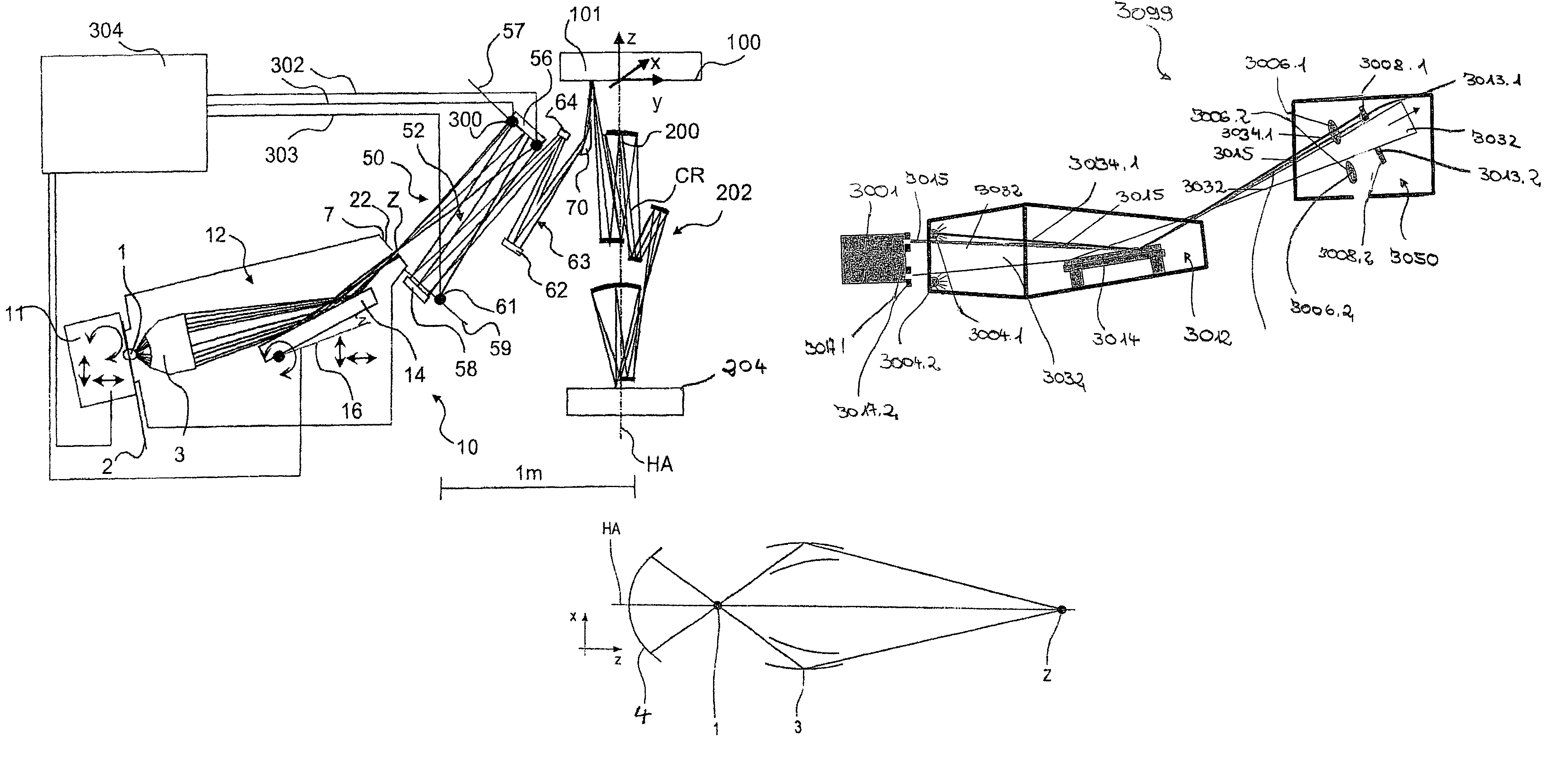
[0063]In FIG. 1a, an EUV projection exposure system is shown, in which sensors are disposed on a first optical element with first raster elements for detection of light striking a support element. The EUV projection exposure system comprises a light source 1 with a source plasma emitting EUV radiation, a collecting optical component, i.e., a so-called collector 3, which is formed as a nested collector according to WO 02 / 065482, the disclosure content of which is included to the full extent in the present application. The collector 3 images the light source 1 situated in an object plane 2 of an illumination system 10 into an intermediate image Z of the light source 1 or a secondary light source in a plane 7 conjugated to the object plane 2. A physical diaphragm 22 is disposed in or near the plane 7.

[0064]In the embodiment shown, the light source 1, which can be, for example, a laser-plasma source or a plasma discharge source, is disposed in the object plane 2 of the illumination syst...


PUM

PropertyMeasurementUnit
wavelengthaaaaaaaaaa
wavelengthsaaaaaaaaaa
wavelength rangeaaaaaaaaaa

Abstract

There is provided an illumination system that includes (a) a light source that emits light having a wavelength ≦193 nm, where the light provides a predetermined illumination in a plane distant from the light source and defines a used area in the plane, and (b) a sensor, situated in or near the plane, for detecting light outside the used area.

Description

CROSS-REFERENCE TO RELATED APPLICATIONS[0001]The present application is a continuation-in-part of PCT / EP2003 / 10605, filed Sep. 24, 2003, the content of which is herein incorporated by reference.BACKGROUND OF THE INVENTION[0002]1. Field of the Invention[0003]The invention concerns an illumination system for wavelengths of ≦193 nm with a light source that provides a predetermined illumination A in a plane. The illumination system comprises a first optical component with first raster elements, which are arranged on a support element, wherein the first optical component is disposed in, or in the vicinity of, the plane in which the illumination is provided. The wavelength preferably lies in the wavelength range of ≦100 nm, particularly in the wavelength range which can be used for EUV lithography, i.e., in the range of 11 to 14 nm, in particular, at 13.5 nm.[0004]2. Description of the Related Art[0005]In order to still further reduce the structural widths for electronic components, in pa...

Claims


Application Information

Patent Timeline
Patent Type & Authority Patents(United States)
IPC IPC(8): G01G1/00G01J1/42G03F7/20
CPCG03F7/70141G03F7/70558G03F7/7085
Inventor SINGER, WOLFGANGANTONI, MARTINWANGLER, JOHANNESWEISS, MARKUSBANINE, VADIM YEVGENYEVICHDIERICHS, MARCELMOORS, ROELSCHUSTER, KARL HEINZSCHOLZ, AXELBOSSELMANN, PHILIPPWARM, BERND
Owner CARL ZEISS SMT GMBH
Why Eureka
Try Eureka