
Device and method for quality assurance and online verification of radiation therapy

a radiation therapy and quality assurance technology, applied in the field of devices and methods for quality assurance and online verification of radiation therapy apparatuses, can solve the problems of inability to perform in real-time, time-consuming process, pixel ionization chamber, etc., to achieve more transparent chamber, reduce leakage, and improve radiation measurement transparency

Active Publication Date: 2009-01-13
DIPARTIMENTO DI FISICA SPERIMENTALE OF THE UNIV DEGLI STUDI DI TORNI +2
View PDF9 Cites 51 Cited by
  • Summary
  • Abstract
  • Description
  • Claims
  • Application Information

AI Technical Summary

Benefits of technology

The patent describes a radiation monitor that can measure the radiation delivered to a target by a radiation device. The monitor contains a set of pixel ion chambers made up of a top electrode, a mid layer, and a segmented electrode. The mid layer is laminated to the top electrode and segmented electrode by adhesive dots to provide ventilation channels for the chambers. The monitor can be positioned between the radiation device and the target to measure the fluency rate of the radiation in real-time. The dose of radiation delivered to the target can be determined from the measured radiation and compared to a target treatment dose. The monitor is designed to provide accurate and reliable measurement of radiation dosage during treatment.

Problems solved by technology

This process is time consuming, and cannot be performed in real-time.
However, this known pixel ionization chamber presents some disadvantages.
One disadvantage is the presence of mechanical instability.
Mechanical deformation or microphonic effect can affect the distance between electrodes in a significant way, thereby negatively affecting the accuracy and precision of the date.
Another disadvantage with the known systems is the transparency.
The significant amount of copper produces backscattering, and reduces transparency, thereby reducing the applicability of this device as a transmission chamber.

Method used


Image

  • Device and method for quality assurance and online verification of radiation therapy
  • Device and method for quality assurance and online verification of radiation therapy
  • Device and method for quality assurance and online verification of radiation therapy

Examples


Embodiment Construction

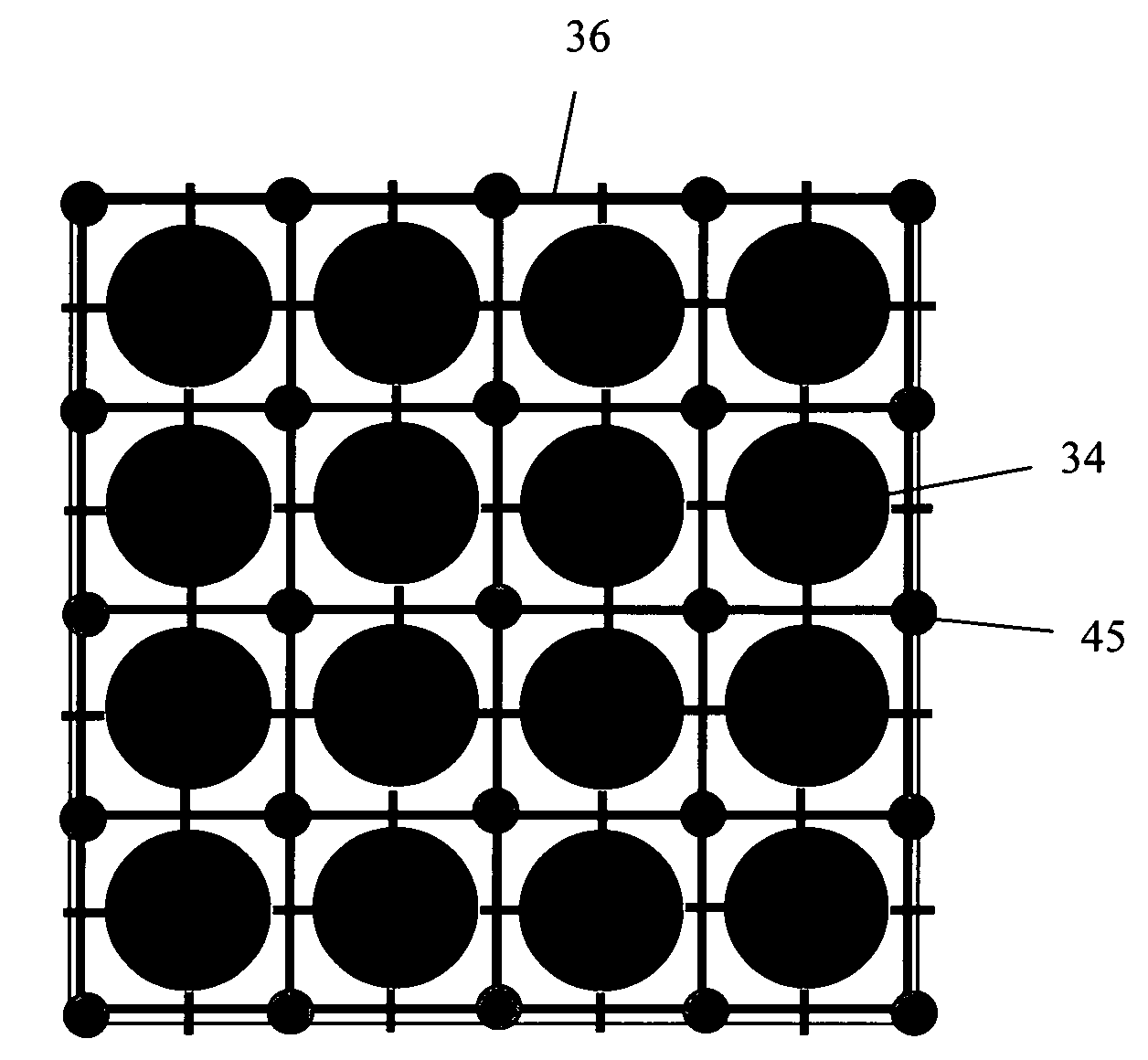
[0018]A monitoring device for measuring radiation in real time is described. The monitoring device can be used for monitoring the fluency rate produced by a radiation device. In operation the monitoring device is positioned between the radiation device and the target, such as a patient receiving radiation treatment. In such a position, the device measures the fluency rate and the corresponding radiation dose can be determined in real time. The following description is of the preferred embodiment of the present invention.

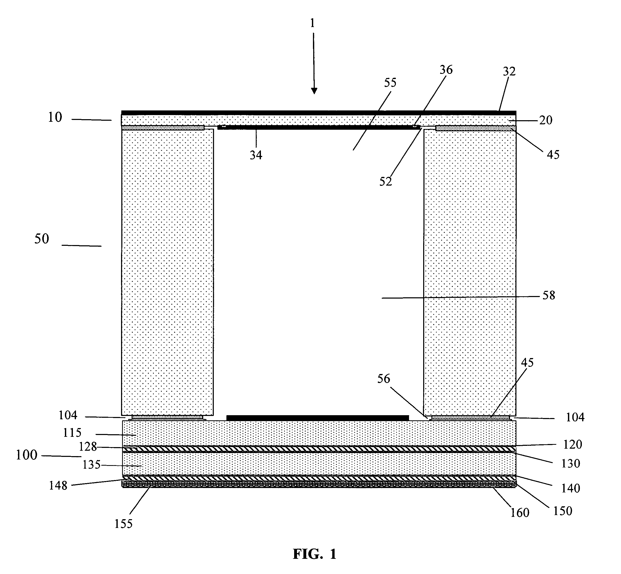
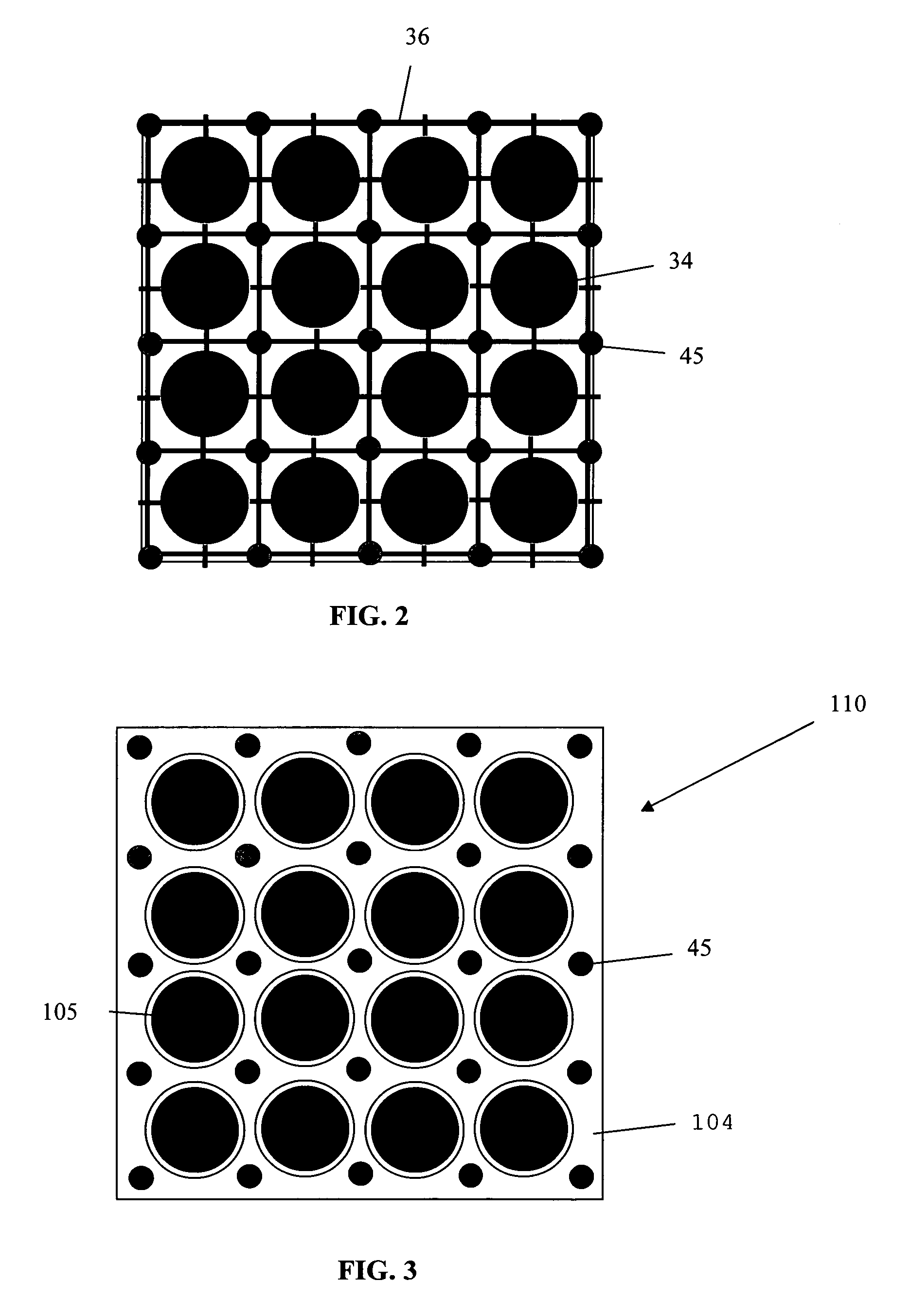
[0019]The monitoring device is made up of an array or matrix of pixel ion chambers. FIG. 1 shows the side view of the structure of a single pixel ion chamber 1 constructed in accordance with the present invention. The pixel ion chamber 1 has a top electrode 10, a mid layer 50, and a segmented electrode 100.

[0020]The top electrode 10 has a polyimide layer 20 sandwiched on both sides by carbon layers 32 and 34. The top electrode could be made from any material, dependi...


PUM


Abstract

A radiation monitor and method of monitoring the radiation delivered to a target by a radiation device is described. The radiation monitor contains a set or matrix of pixel ion chambers. The pixel ion chambers are preferably constructed of a top electrode and a segmented electrode connected to the top electrode through a mid layer. The plurality of pixel ion chambers is formed within the mid layer extending from the top electrode to the segmented electrode. The mid layer is laminated to the top electrode and segmented electrode by an array of adhesive dots, wherein the adhesive dots are dimensioned and positioned on the mid layer to provide ventilation slits or channels for the ion chambers.

Description

CROSS REFERENCE TO RELATED APPLICATION[0001]This application claims the benefit of U.S. Provisional Patent Application No. 60 / 685,712, filed May 27, 2005, the entirety of which is hereby incorporated by reference into this application.FIELD OF THE INVENTION[0002]The present invention is related to a device and method for quality assurance and online verification of a radiation therapy apparatus such as an IMRT apparatus.STATE OF THE ART[0003]When delivering radiotherapy to a patient, it is of the utmost importance to ensure that the prescribed dose is delivered to the target volume.[0004]Radiographic X-ray film has been used extensively for performing quality assurance of radiation therapy apparatuses. A thin plastic film with a radiation sensitive emulsion (e.g. silver bromide, AgBr grains suspended in gelatin) is irradiated, and ionization of AgBr grains forms an image, after development. Optical density must be measured using a densitomer. This process is time consuming, and cann...

Claims


Application Information

Patent Timeline
Patent Type & Authority Patents(United States)
IPC IPC(8): G01T1/18H01J47/00
CPCA61N5/1048G01T1/2935H01J47/02
Inventor FRITSCH, ERNSTFRIEDL, FRIEDRICHGOMOLA, IGORPERONI, CRISTIANAFLAVIO, MARCHETTODONETTI, MARCOCIRIO, ROBERTO
Owner DIPARTIMENTO DI FISICA SPERIMENTALE OF THE UNIV DEGLI STUDI DI TORNI
Learn More