
Generation and use of system level defect tables for main memory

a technology of main memory and defect tables, applied in the direction of digital storage, dc motor speed/torque control, instruments, etc., can solve the problems of inefficient replacement of modules in this manner, defects that may develop over time, and the least amount of memory failures can be expected, so as to increase the overall reliability of memory systems

Active Publication Date: 2009-01-13
HEWLETT-PACKARD ENTERPRISE DEV LP
View PDF6 Cites 49 Cited by
  • Summary
  • Abstract
  • Description
  • Claims
  • Application Information

AI Technical Summary

Benefits of technology

[0009]Embodiments of the present invention provide techniques for increasing the overall reliability of memory systems that utilize modular memory modules.

Problems solved by technology

Unfortunately, with such a large number of modules in use (each having a number of memory chips), at least some amount of memory failures can be expected.
While factory testing at the device (IC) level can catch many defects and, in some cases, replace defective cells with redundant cells (e.g., via fusing), some defects may develop over time after factory testing.
If a memory failure is detected, the entire module will be replaced, even if the failure is limited to a relatively small portion of the module.
Replacing modules in this manner is inefficient in a number of ways, in addition to the possible interruption of computing and loss of data.
On the one hand, the replacement may be performed by repair personnel of the system vendor at substantial cost to the vendor.
On the other hand, the replacement may be performed by dedicated personnel of the customer, at substantial cost to the customer.
A costly solution to increase fault tolerance is through redundancy.
However, this solution can be cost prohibitive, particularly as the overall memory space increases.
However, this approach may significantly impact performance by reducing the available memory by an entire device or DIMM, regardless of the amount of memory locations found to be defective.

Method used


Image

  • Generation and use of system level defect tables for main memory
  • Generation and use of system level defect tables for main memory
  • Generation and use of system level defect tables for main memory

Examples


Embodiment Construction

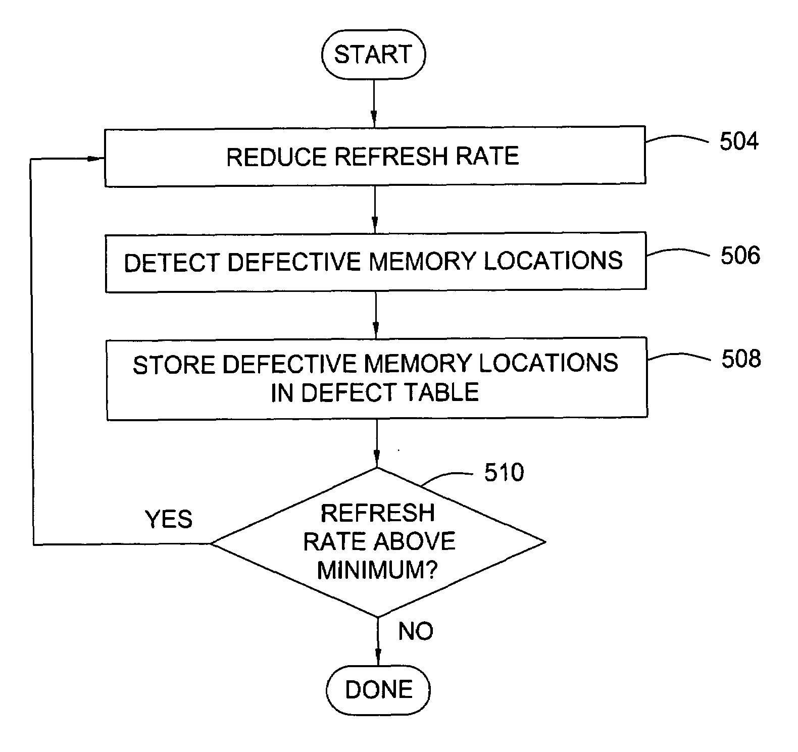
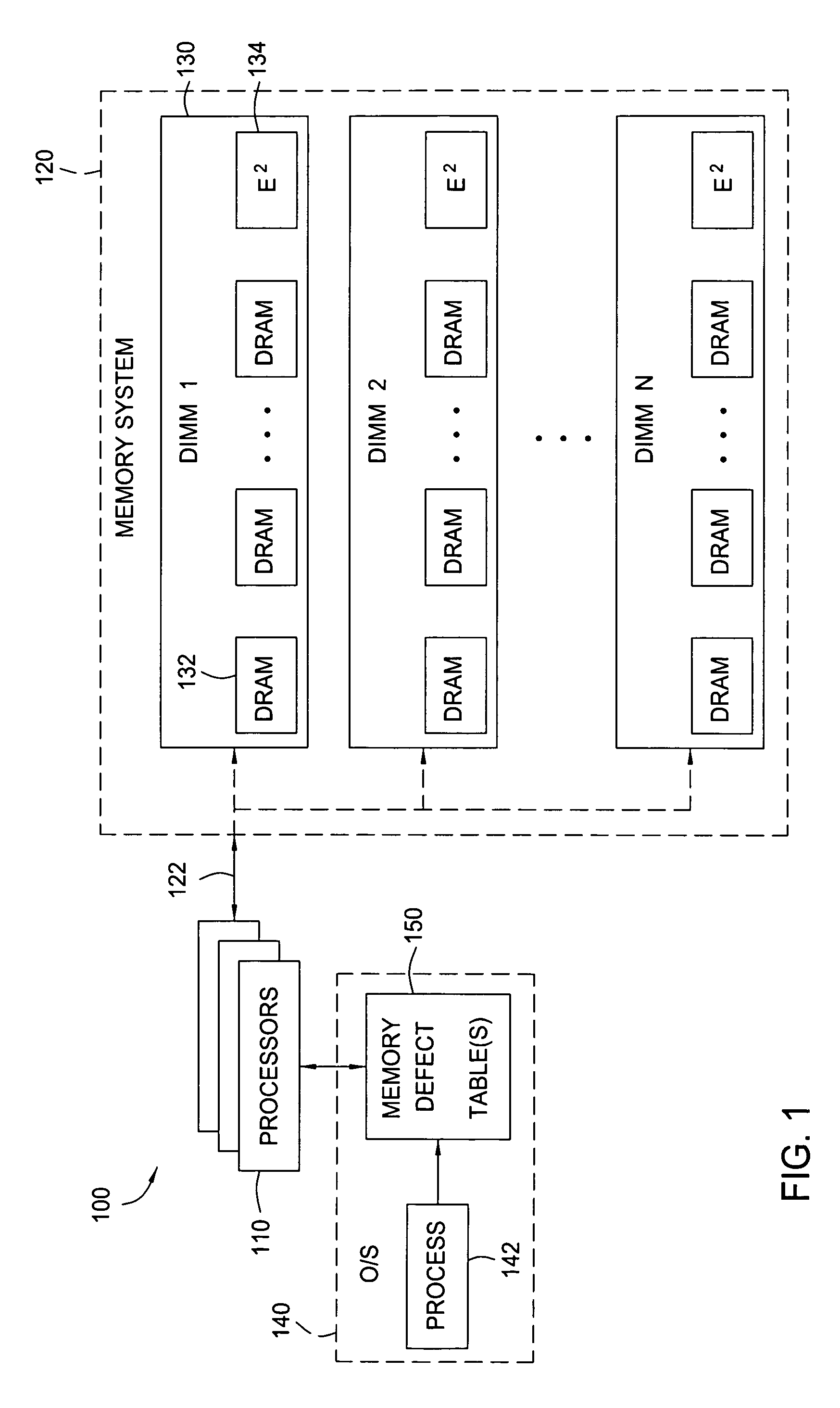
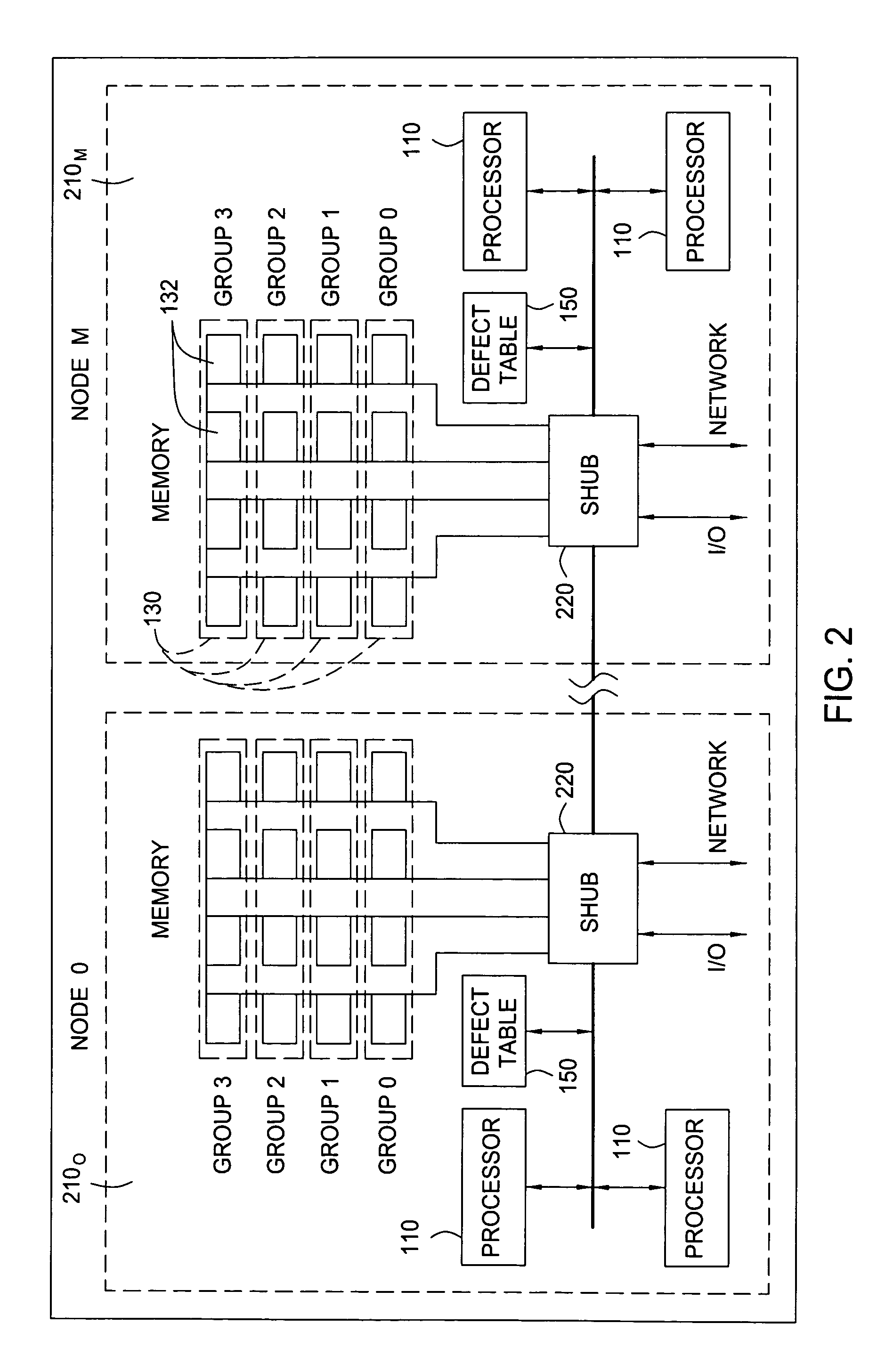
[0020]Embodiments of the present invention generally provide methods and apparatus for maintaining and utilizing system memory defect tables that store information identifying defective memory locations in memory modules. For some embodiments, the defect tables may be utilized to identify and re-map defective memory locations to non-defective replacement (spare) memory locations as an alternative to replacing an entire memory module. For some embodiments, some portion of the overall capacity of the memory module may be allocated for such replacement. As a result, memory modules may be made more fault-tolerant and systems more reliable. Further, this increased fault-tolerance may significantly reduce service requirements (e.g., repair / replacement) and overall operating cost to the owner and / or vendor.

[0021]Embodiments of the present invention will be described below with reference to defect table to identify defective memory locations in dual inline memory modules (DIMMs). However, t...


PUM


Abstract

Methods and apparatus for maintaining and utilizing system memory defect tables that store information identifying defective memory locations in memory modules. For some embodiments, the defect tables may be utilized to identify and re-map defective memory locations to non-defective replacement (spare) memory locations as an alternative to replacing an entire memory module. For some embodiments, some portion of the overall capacity of the memory module may be allocated for such replacement.

Description

BACKGROUND OF THE INVENTION[0001]1. Field of the Invention[0002]Embodiments of the present invention generally relate to techniques for increasing the overall reliability of memory systems that utilize modular memory modules.[0003]2. Description of the Related Art[0004]Computer system performance can be increased by increasing computing power, for example, by utilizing more powerful processors or a larger number of processors to form a multi-processor system. It is well established, however, that increasing memory in computing systems can often have a greater effect on overall system performance than increasing computing power. This result holds true from personal computers (PCs) to massively parallel supercomputers.[0005]High performance computing platforms, such as the Altix systems available from Silicon Graphics, Inc. may include several tera-bytes (TBs) of memory. To provide such a large amount of memory, such configurations may include many thousands of modular memory modules,...

Claims


Application Information

Patent Timeline
Patent Type & Authority Patents(United States)
IPC IPC(8): G06F11/00
CPCG11C29/44G11C29/88H02P7/281G11C5/04G11C2029/1208
Inventor FOUQUET-LAPAR, MATTHIAS
Owner HEWLETT-PACKARD ENTERPRISE DEV LP
Learn More