Variably operated valve system for compression ignition engine

a valve system and ignition engine technology, applied in the direction of valve details, valve arrangements, valve drives, etc., can solve the problems of inability to solve inconveniences during engine start, and insufficient effective compression ratio, so as to achieve more substantial effective compression ratio, increase effective compression ratio, and improve reliability of engine start

Inactive Publication Date: 2009-01-20
HITACHI LTD
View PDF13 Cites 8 Cited by
  • Summary
  • Abstract
  • Description
  • Claims
  • Application Information

AI Technical Summary

Benefits of technology

[0006]It is noted that the IVC described in the specification can be defined as the intake valve closure timing as described above but is not a timing that the intake valve is completely closed but may be the timing at which an effective lift interval not including a ramp interval not including a ramp interval is completed. If the effective closure timing is set in the proximity to the BDC, a substantial closure timing at which a lift acceleration interval is completed can be deemed to the BDC and, thus, the effective compression ratio can more substantially be increased. In the variably operated valve system for the compression ignition engine according to the present invention including the control section to control the IVC to be detached from the BDC (bottom dead center) in accordance with the engine driving condition, even if the control section has failed, the mechanical bias section always sets the IVC to be in a state near to the BDC. Hence, the effective compression ratio can be maintained at a highest level that the engine is provided and the reliability of the engine start can remarkably be increased. Furthermore, eve if the mechanical bias section cannot set the IVC to be in the proximity to the BDC due to an inconvenience in the control section, the startability (start characteristic) guarantee fail-safe control logic can assuredly start the engine.

Problems solved by technology

However, in a case where, in each of the previously proposed variably operated systems described above, a mechanical failure such as a failure in an electrical system of a hydraulic switching valve or a fixation (lock) of the hydraulic switching valve occurs or a failure in a hydraulic system thereof occurs, the intake valve closure timing (IVC) is separated (detached or varied) from a bottom dead center (BDC) position during the engine start so that the effective compression ratio is not sufficiently raised and a start failure may occur.
However, if the stepping motor is fixed, the inconveniences during the start of the engine cannot be solved In addition, in the latter Japanese Paper, various variably operated valve systems have been proposed.
Thus, the inconveniences during the start of the engine cannot still be solved.

Method used


Image

  • Variably operated valve system for compression ignition engine
  • Variably operated valve system for compression ignition engine
  • Variably operated valve system for compression ignition engine

Examples


Embodiment Construction

[0025]Reference will hereinafter be made to the drawings in order to facilitate a better understanding of the present invention.

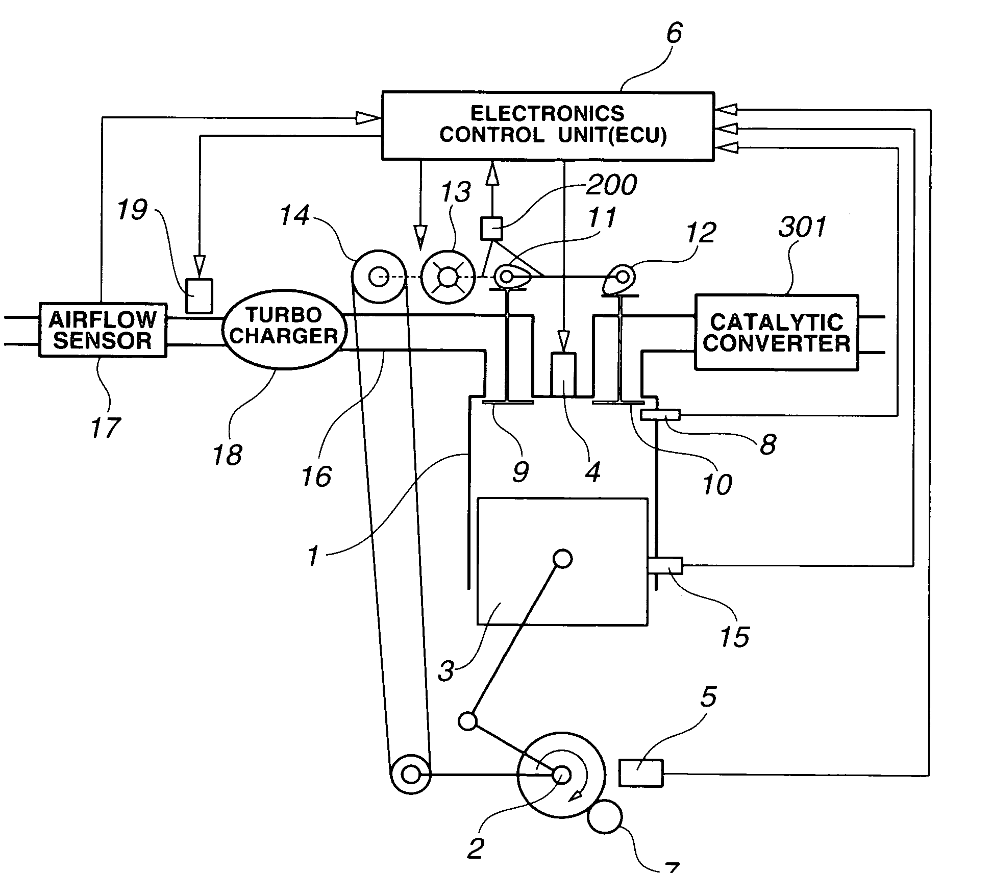
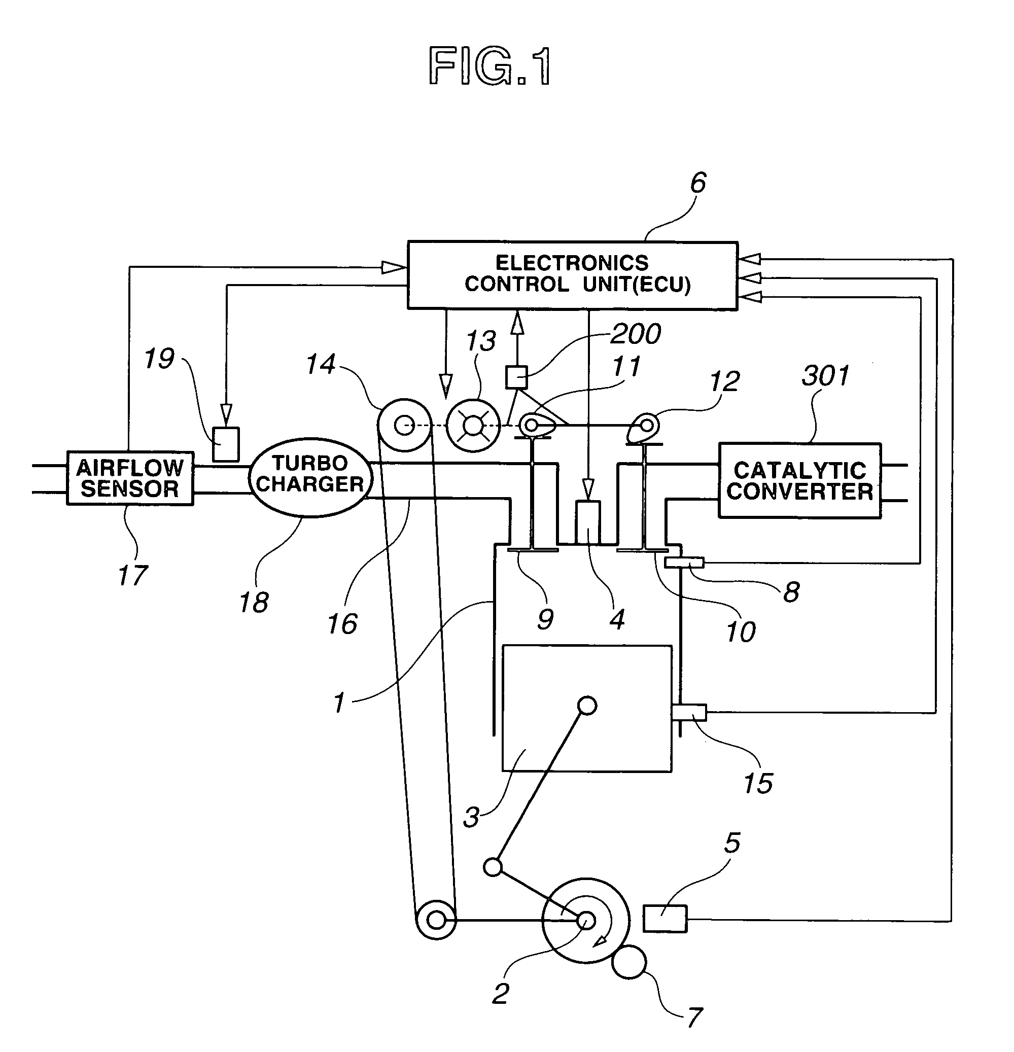
[0026]First, a variably operated valve system of a four-stroke Diesel engine will be described with reference to FIG. 1. A crankshaft 2 of an engine 1 is revolved in a clockwise direction as viewed from FIG. 1. A state in which a cylinder piston 3 is located at a bottom position (lowest position) indicates a bottom dead center (BDC) which is represented in 180 degrees in crank angle (CA). When crankshaft 2 is revolved and piston 2 has reached to a top dead center (a highest position as viewed from FIG. 1), it indicates a top dead center (TDC) and its crank angle (CA) is expressed to be 360 degrees. In a case of an ordinary Diesel combustion, fuel is injected within a cylinder from a fuel injection valve 4 and a self-ignition due to a high temperature of gas occurs and fuel is combusted. In a case of a pre-mixture compression ignition, fuel is injected from ...


PUM


Abstract

In a variably operated valve system for a compression ignition engine, an adjustment mechanism is controlled by means of a control section to detach an intake valve closure timing from a bottom dead center in accordance with an engine driving condition, and an engine start securing section guarantees an engine start even at least one of cases during a failure in the control section, during a stop of the engine, and during a start of the engine.

Description

BACKGROUND OF THE INVENTION[0001]The present invention relates to a variably operated valve system for an intake valve or an exhaust valve of a reciprocating engine and, more particularly, relates to the variably operated valve system suitable for use in a compression ignition engine such as a four-stroke and two-stroke Diesel engine.[0002]Recently, a variably operated valve system which varies a lift and open and closure timings of the intake valve(s) and / or the exhaust valve(s) in accordance with an engine driving condition has widely been utilized in order to control a charge efficiency of the engine, an effective compression ratio, and a residual gas quantity and to improve an engine performance and an emission performance. In a Diesel engine or a pre-mixture compression ignition engine, due to a temperature rise of gas generated along with a compression stroke of the engine, an injected fuel is self ignited. The self-ignition of fuel is carried out only under such a condition t...

Claims


Application Information

Patent Timeline
Patent Type & Authority Patents(United States)
IPC IPC(8): F01L1/34
CPCF01L1/3442F01L13/0026F01L2001/0537F01L2001/34483F01L2013/0073F01L2800/00F01L2820/032F02D13/02F01L1/34F01L13/00
Inventor NAKAMURA, MAKOTOHARA, SEINOSUKESUGA, SEIJIWATANABE, MASAHIKOHOKARI, TOMIO
Owner HITACHI LTD
Why Eureka
Try Eureka