Hair iron
a technology of hair iron and hair shaft, applied in the field of hair iron, to achieve the effect of efficient winding and reforming of hair
- Summary
- Abstract
- Description
- Claims
- Application Information
AI Technical Summary
Benefits of technology
Problems solved by technology
Method used
Image
Examples
first modified embodiment
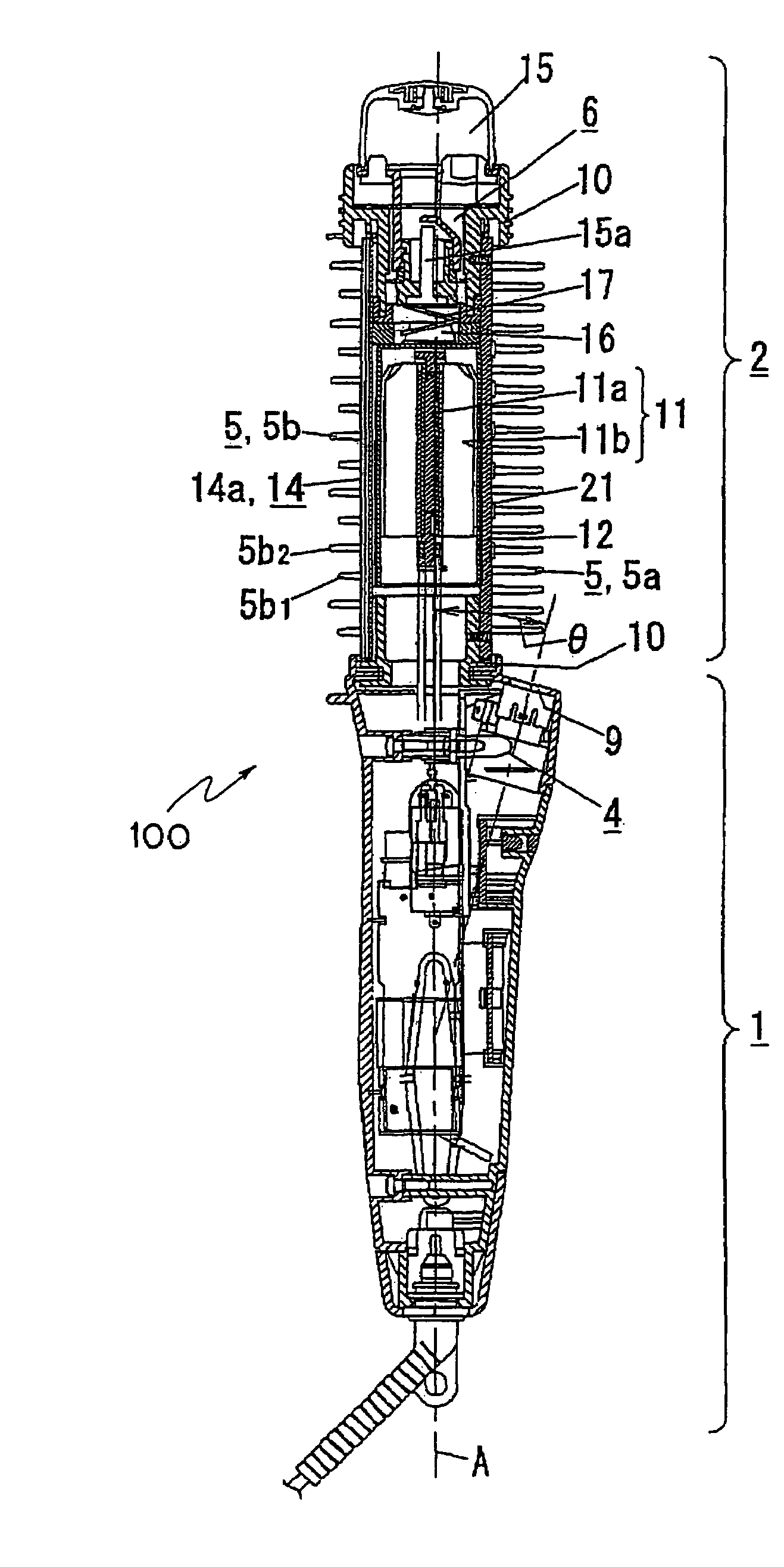
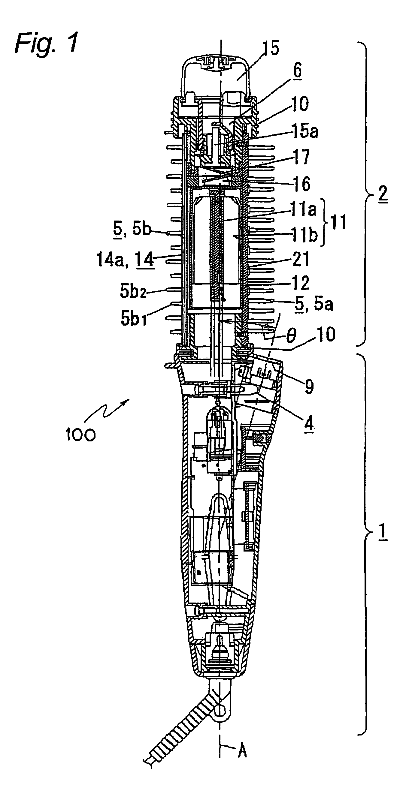
[0072]FIG. 8 is a front sectional view of a hair iron 110 of a The hair iron 110 is different from the hair iron 100 (FIG. 1) in a point that bristles 5 around a position C near an outlet 9 are removed among the bristles provided on an outer peripheral plane of the hair-care section 2. In other words, the bristles 5 are positioned separately by distances more than a predetermined distance (for example, 2 to 3 centimeters) from the position C near the outlet 9. The reason is explained here. If the bristles 5 exist near the position C, they are exposed to negative ions for a long time to be charged negatively, so that negative ions which will pass between the bristles 5 are repelled or blown away. Therefore, the amount of negative ions which would arrive to hair is liable to be decreased. Then, bristles 5 near the position C are removed so as to emit negative ions efficiently towards the entire hair. The hair iron 110 is similar to the above-mentioned hair iron 100 (FIG. 1) except th...
second modified embodiment
[0090]In the second modified embodiment, the structure of the hair iron is similar to that of the above-mentioned one explained with reference to FIG. 1 and the like, except the above-mentioned characteristics. Therefore, in the hair irons 120, 130 and 140, the grip has the switch handle of slide type. Therefore, emission of negative ions to hair can be performed independently of or in parallel to the hair care using the heater 11, or negative ions can be adhered without heating hair. Thus, the effect of negative ions to hair can be enjoyed selectively, and a use can use the hair iron in various ways.
[0091]FIG. 14 is a front sectional view of a hair iron 170 of a third modified embodiment. The hair iron 170 is obtained by modifying the hair iron of the second modified embodiment (FIGS. 9 to 13). A difference of the hair iron 170 from the second modified embodiment is that an outlet 9 is provided in an iron plate 33 as a holding plane 24. In the structure, negative ions can be emitte...
fourth modified embodiment
[0092]FIGS. 15A, 15B and 15C are a front sectional view, a front view and a vertical sectional view of a hair iron 180 according to a The hair iron 180 is also a modified embodiment of the above-mentioned holding-type hair iron. A difference thereof from the above-mentioned holding-type hair iron is that a negative ion generator 4 is built in the grip 1 of the main block 30 and that an outlet 9 emitting negative ions opens towards the hair-care section 2 for holding hair. In particular, the negative ion generator 4 is built in the grip 1 in a position near the hair-care section 2. Further, the outlet 9 is provided between the grip 1 and the hair-care section 2, and it faces the presser foot plate 34 of the presser foot block 31. By setting the negative ion generator 4 in the grip 1, the hair-care section 2 can be made compact and with a light weight. Therefore, the hair iron can fabricated to have a various shape, a compact size and a light weight, and this makes it easier for a us...
PUM
 Abstract
Description
Claims
Application Information
 - R&D
- Intellectual Property
- Life Sciences
- Materials
- Tech Scout
- Unparalleled Data Quality
- Higher Quality Content
- 60% Fewer Hallucinations
Browse by: Latest US Patents, China's latest patents, Technical Efficacy Thesaurus, Application Domain, Technology Topic, Popular Technical Reports.
© 2025 PatSnap. All rights reserved.Legal|Privacy policy|Modern Slavery Act Transparency Statement|Sitemap|About US| Contact US: help@patsnap.com


