
Embolism filter with self-deployable guidewire stop

a filter and guidewire stop technology, applied in the field of embolitic filter devices, can solve the problems of filter deployment that cannot be standardized, and achieve the effect of convenient vasculature maneuverability

Active Publication Date: 2009-01-20
CARDIOVASCULAR SYST INC
View PDF27 Cites 4 Cited by
  • Summary
  • Abstract
  • Description
  • Claims
  • Application Information

AI Technical Summary

Benefits of technology

The invention is an embolism filter that can be deployed on a guidewire in the body to prevent the formation of blood clots. The filter has self-deploying stops that can be attached to the guidewire at different locations, allowing it to be placed at any desired location along the guidewire. The stops can be made of a spring or a cushion made of flexible material. The filter can also have a fluid release mechanism or an inflatable member to control its placement. The invention provides an improved method for protecting the blood vessels from embolisms during medical procedures.

Problems solved by technology

However, the filter can also be deployed with non-standard guide wires, for example, with a stepped or tapered diameter or with stops, ignoring or utilizing these stops, depending on the filter geometry.

Method used


Image

  • Embolism filter with self-deployable guidewire stop
  • Embolism filter with self-deployable guidewire stop
  • Embolism filter with self-deployable guidewire stop

Examples


Embodiment Construction

Filter with Spring Stops

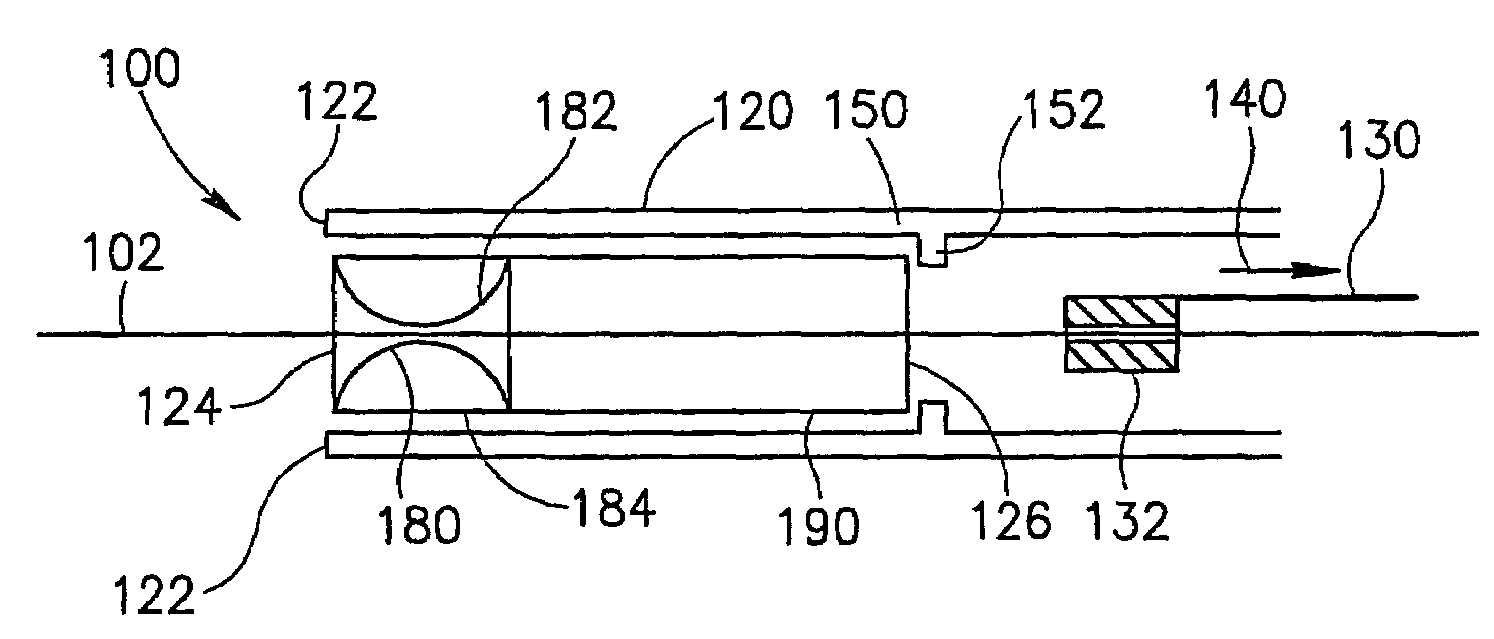
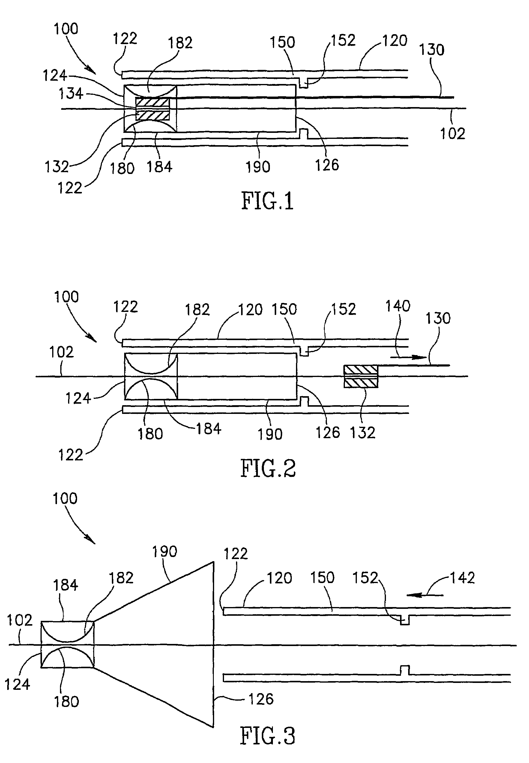
[0047]FIG. 1 is a cross sectional view of a filter 100 contained within a delivery sheath 150, in accordance with an exemplary embodiment of the invention. In an exemplary embodiment, filter 100 comprises stops 180 and 182 that are restrained from contacting a guidewire 102 by a restrainer 132. During positioning of filter 100, optional stabilizers 152 that project from a sheath wall 120 press against filter 100 to advance filter 100 along guidewire 102.

[0048]Filter 100 and / or stops 180 and 182 may be designed in a variety of materials and shapes for example a range of guidewire diameters, for example a range of 1:1.5, 1:2 or 1:4 or any smaller, intermediate or larger ratio of diameters. Alternatively or additionally, in any specific design, filter 100 and / or stops 180 and 182 may be manufactured to encompass a guidewire of a specific diameter. Guidewire diameters for which filter 100 and / or stops 180 and 182 can be designed include, for example:

[0049]i) smal...


PUM


Abstract

An embolism filter adapted to selectively stop an embolism filter along a length of guidewire, including a filter adapted to encircle a guidewire and at least one self-deploying stop attached to the filter and which selectively stops movement of said filter.

Description

RELATED APPLICATIONS[0001]The present application is a US National Phase of PCT Application No. PCT / IL2003 / 000144, filed on Feb. 25, 2003, published as WO 2004 / 012628. This application also claims the benefit under 35 USC §119(e) of U.S. provisional application 60 / 400,801, filed on Aug. 05, 2002, the disclosure of which is incorporated herein by reference.FIELD OF THE INVENTION[0002]The present invention relates to devices for filtering embolitic material from circulating blood.BACKGROUND OF THE INVENTION[0003]Embolitic material comprising calcium, intimal debris, pieces of an artheromatous plaque and / or thrombi, has the potential of migrating and causing distal tissue damage, for example, stroke and / or myocardial infarction. (See Topol, E. J. and Yadov, J. S., “Recognition of the Importance of Embolization in Athereosclerotic Vascular Disease”, Circulation 2000, 101:570.) Embolic material with the potential of distal tissue damage is often released during vascular interventional pr...

Claims


Application Information

Patent Timeline
Patent Type & Authority Patents(United States)
IPC IPC(8): A61M29/00A61F2/958A61F2/01A61F2/02
CPCA61F2/013A61M25/09A61F2002/015A61F2250/0003A61M2025/09125A61M2025/09183A61F2002/018A61F2230/0006A61F2230/0067A61F2002/011A61M2025/09075A61M2025/09008A61M2210/12A61F2/011
Inventor ROSENSCHEIN, URIOFIR, GIL
Owner CARDIOVASCULAR SYST INC
Learn More