
Flexible appliance and related method for orthogonal, non-planar interconnections

a flexible appliance and non-planar technology, applied in the direction of polarised antenna unit combination, association of printed circuit non-printed electric components, incorporation of printed electric components, etc., can solve the problems of inability to perform manual processes, process is extremely time-consuming and can only be performed manually, and does not lend itself well

Active Publication Date: 2009-01-20
HARRIS CORP
View PDF17 Cites 5 Cited by
  • Summary
  • Abstract
  • Description
  • Claims
  • Application Information

AI Technical Summary

Problems solved by technology

In the manufacture of a device having multiple interfaces requiring an individual electrical connection therebetween, this process is extremely time consuming and can only be performed manually.
In the manufacture of a device having multiple interfaces requiring an individual electrical connection therebetween, this process can be extremely time consuming and doesn't lend itself well to being automated for several reasons.
Particularly, it is too difficult and expensive to convert existing automated machinery to perform the multiple steps required to connect the wire or ribbon from the first interface to the second interface when the size of the device exceeds typical working dimensions.
In addition, the machinery required for automating the connection of the wire or ribbon to the first interface, clipping the wire, and then connecting the wire to the planar conductive element could put too much pressure on the substrate and the dielectric sheet.
The materials comprising the substrate and the dielectric sheet are often compliant and are not strong enough to support the pressure of the machinery.
This is especially problematic considering that the dielectric sheet could be comprised of a foam material.
Further, conventional methods of making the final connection of the wire or ribbons to the first and second interfaces such as automated mass reflow soldering often require pre-heating the first and second interfaces to a high temperature.
This is especially undesirable since the substrate, dielectric sheet, or electronic components disposed on the substrate could be damaged by the high temperature.
Considering that a sheet antenna array can have numerous arrangements of antenna dipole elements and feeds arranged over the expanse of the sheet, the process of individually interconnecting the antenna feeds to the antenna dipole elements is both labor and time intensive.
This is generally considered unsatisfactory.

Method used


Image

  • Flexible appliance and related method for orthogonal, non-planar interconnections
  • Flexible appliance and related method for orthogonal, non-planar interconnections
  • Flexible appliance and related method for orthogonal, non-planar interconnections

Examples


Embodiment Construction

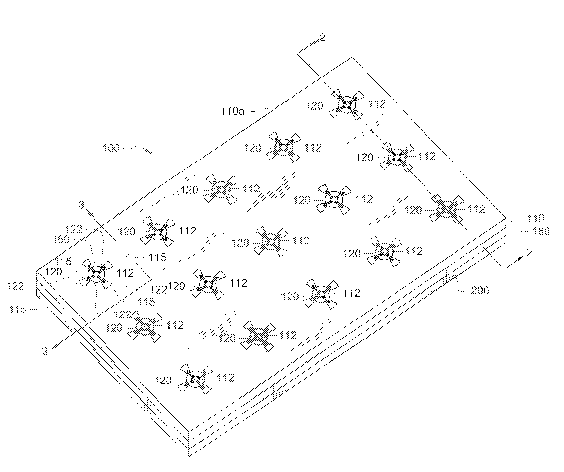
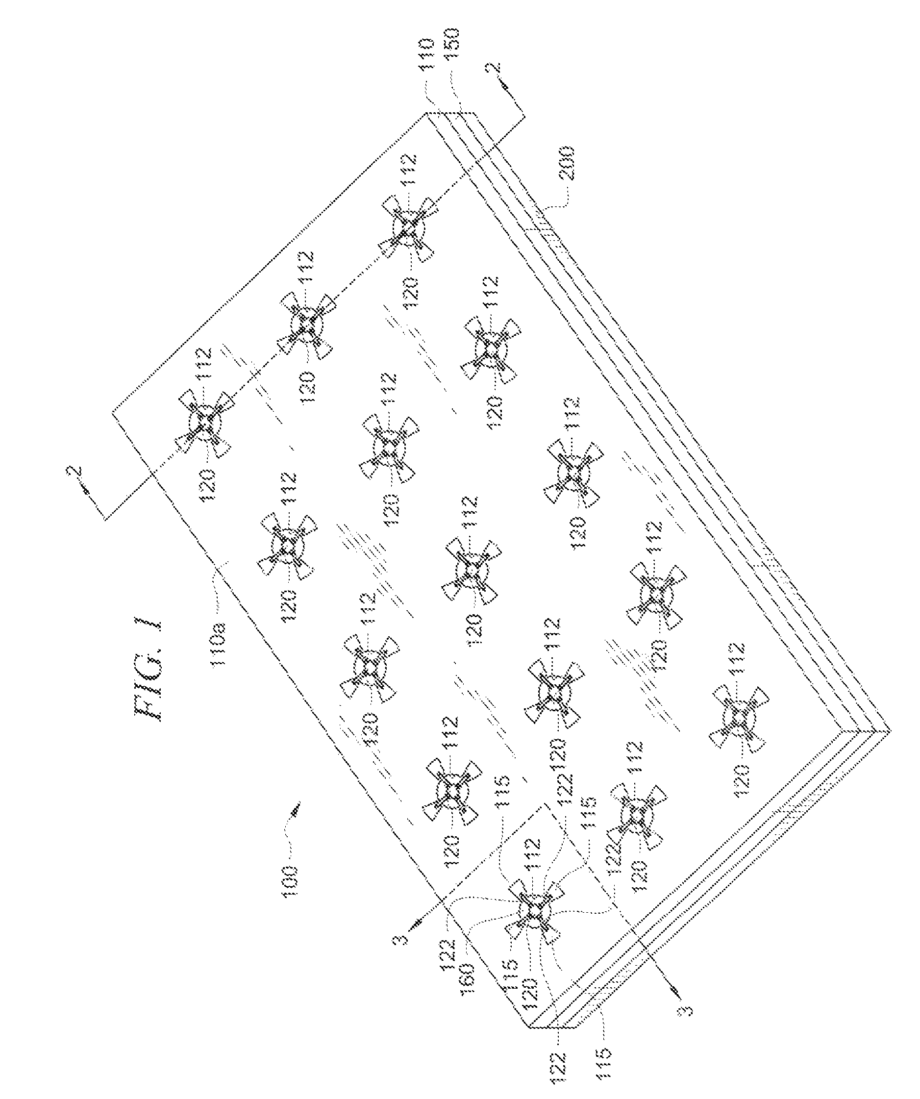
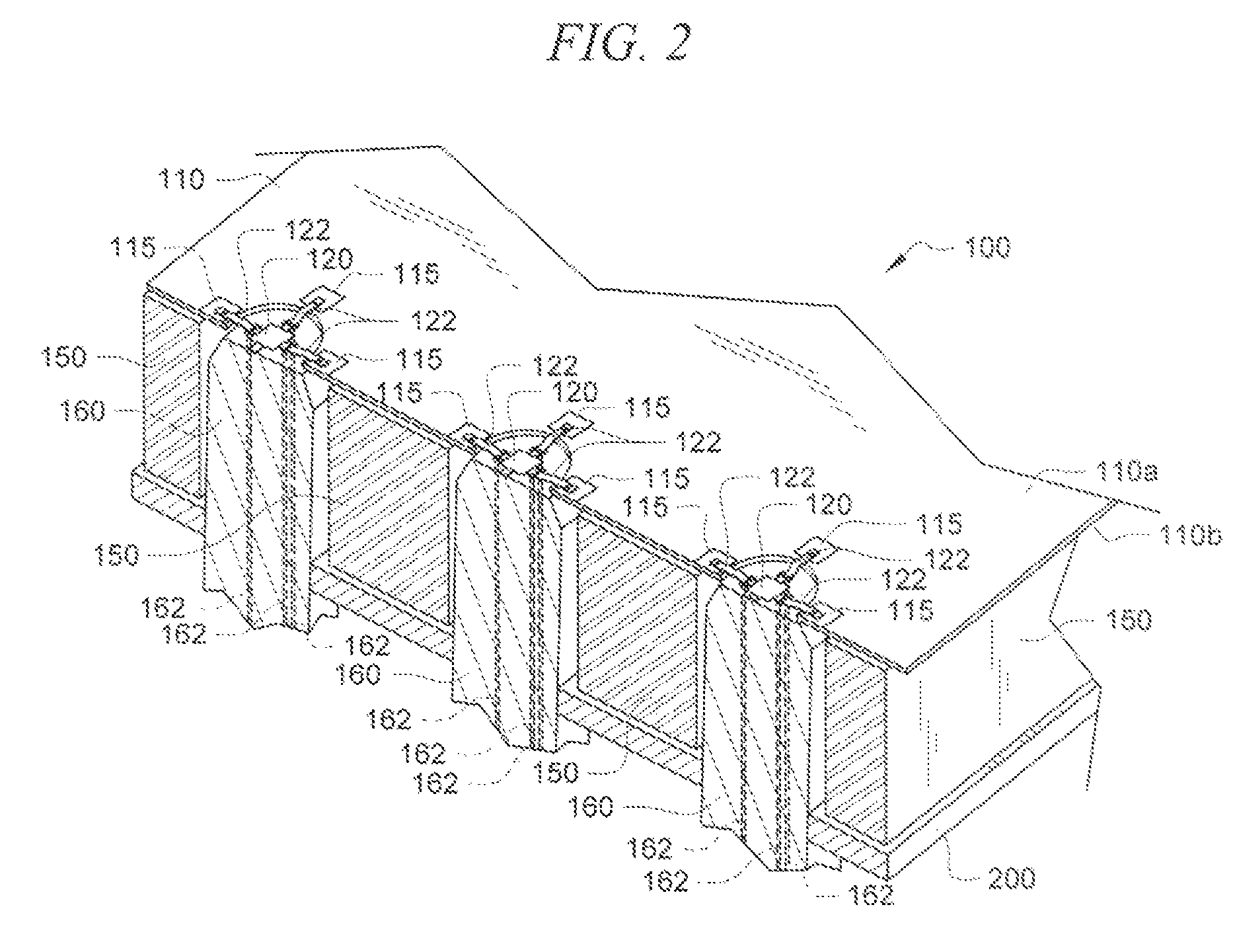
[0030]Referring now to FIGS. 1-2, shown are perspective and cross-sectional perspective views of a composite sheet 100 containing at least one first electronic interface 115 disposed on a substrate 110. The substrate 110 is comprised of a material having desirable mechanical and electrical properties. The desired mechanical properties of the substrate 110 include rigidity, hardness, melting temperature and thermal coefficient of expansion. The desirable electrical properties include a desirable dielectric constant. It should be understood that it is desirable that the dielectric constant of the substrate 110 be low and close to one (1).

[0031]The first electronic interface 115 is electrically interconnected to an associated second electronic interface 161 (best seen in FIGS. 3-5) disposed beneath the substrate 110. The composite sheet 100 is formed from the substrate 110 and at least one additional layer 150 disposed beneath the substrate 110. The additional layer 150 is a second or ...


PUM


Abstract

At least one flexible appliance (120) and related method (300) for orthogonal, non-planar interconnections of at least a first electronic interface (115) disposed on a substrate (110) to an associated second electronic interface (161) positioned beneath the substrate (110). The flexible appliance (120) is comprised of a planar body (121) having at least one electrical connector (122) extending from and orthogonally oriented relative to the planar body (121). In one aspect of the invention, the electrical connector (122) is four electrical connectors (122). There is at least one aperture (112) formed in the substrate (110) for allowing the first electronic interface (115) to be electrically interconnected to the associated second electronic interface (161). The flexible appliance (120) is positioned on the substrate (110) by automated means. Contacts pads (123, 124) on the resilient connector (122) are electrically connected to the second electronic interface (161) and the first electronic interface (115) by automated means such as soldering, thermo sonic bonding, or gap welding.

Description

BACKGROUND OF THE INVENTION[0001]1. Statement of the Technical Field[0002]The invention relates to interconnecting electronic interfaces. More particularly, the invention relates to a flexible appliance and related method for orthogonal, non planar interconnections of at least one first electronic interface disposed on a substrate to an associated second electronic interface positioned beneath the substrate. The flexible appliance and related method compensates for variances in height between the first and second electronic interfaces as well as offsets in the horizontal directions.[0003]2. Background of the Invention[0004]It is known in the art to effect a plurality of electrical connections between interfaces such as a first electronic component and a second electronic component. In such applications, such electrical connections involve manually connecting individual interfaces. In a lower level of assembly, interconnects such as individual wires or ribbons are manually formed, an...

Claims


Application Information

Patent Timeline
IPC IPC(8): H05K1/16
CPCH01Q21/062H01Q21/26H05K1/182H05K2201/10356H05K2201/10681H05K2201/10893
Inventor SMITH, BRIANDEJU, HECTORBURRI, SCOTTCRIDER, LARRY E.KREUZPAINTNER, JOSEPHJANDZIO, GREGORY M.WHYBREW, WALTER M.
Owner HARRIS CORP
Learn More