
Piezoelectrically driven optical lens module

a technology of optical lens module and piezoelectric drive, which is applied in the direction of printers, instruments, camera focusing arrangement, etc., can solve the problems of consuming more power, complicated motor structure, and inability to miniaturize, and achieves excellent image quality, small size, and large torque

Inactive Publication Date: 2009-01-20
IND TECH RES INST
View PDF16 Cites 20 Cited by
  • Summary
  • Abstract
  • Description
  • Claims
  • Application Information

AI Technical Summary

Benefits of technology

[0012]It is another object of the present invention to provide a piezoelectrically driven optical lens module with a reduced size.
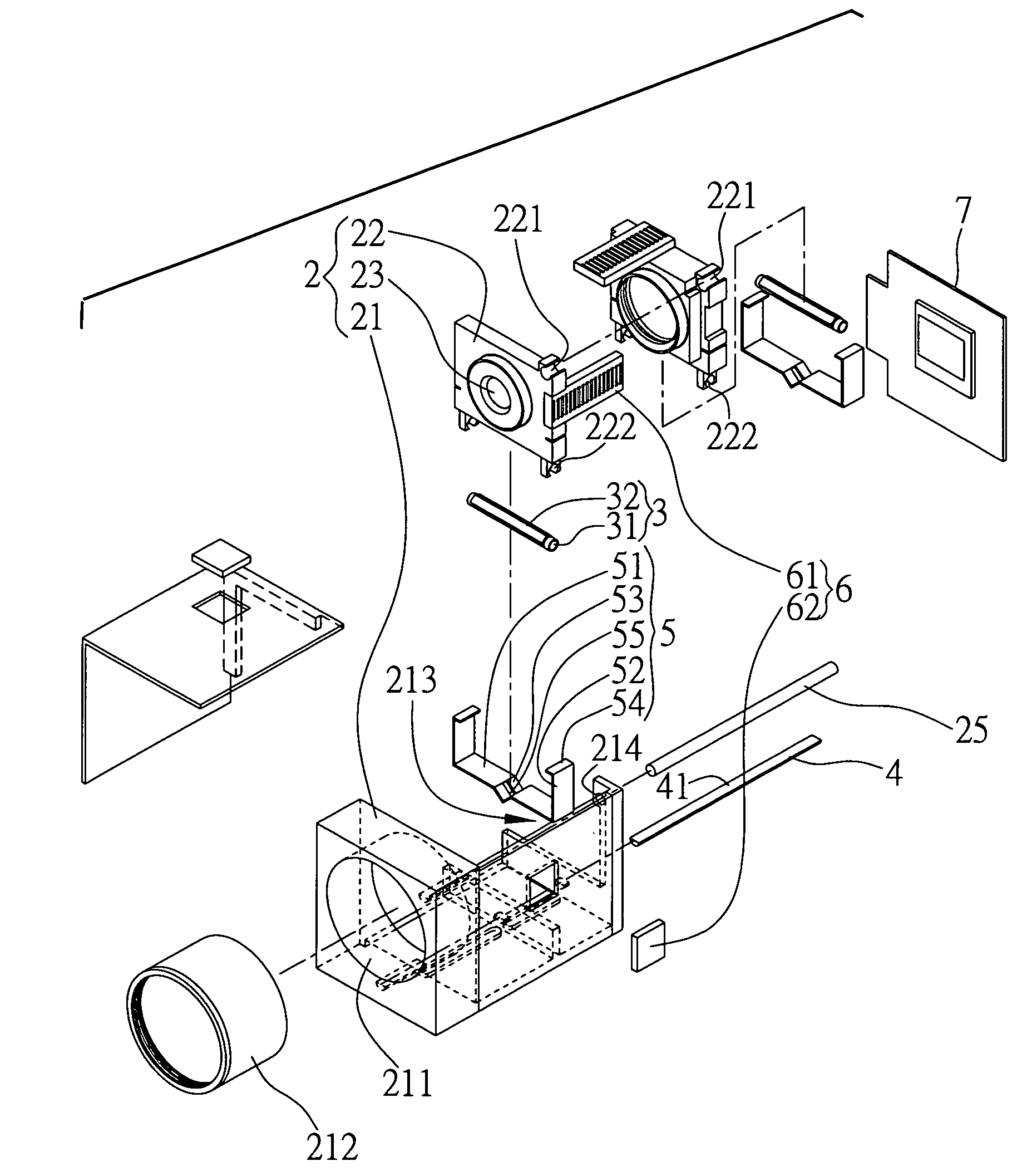
[0023]Compared with the prior art, the present invention uses a piezoelectric driving device capable of acquiring excellent image quality by zooming of the lens element, to achieve large torque and a small size. The piezoelectric driving device is applicable to camera phones. In addition, none of the major constituent elements of the present invention, such as the lens body, the piezoelectric element, the guiding rod, the elastic element and the position detection device, has a complicated design, and thus the object of simplifying constituent elements and providing a rigid construction and easiness of fabrication are also achieved. Furthermore, the major constituent elements of the present invention can be obtained as standard products or one-piece products, therefore the major constituent elements can be easily fabricated. Additionally, each of the constituent elements of the present invention has its own position or engagement site; therefore the constituent elements can be readily assembled. In conclusion, the present invention has overcome drawbacks of prior arts, and therefore, has high industrial applicability.

Problems solved by technology

Thus, the motor structure is complicated, and miniaturization is impossible.
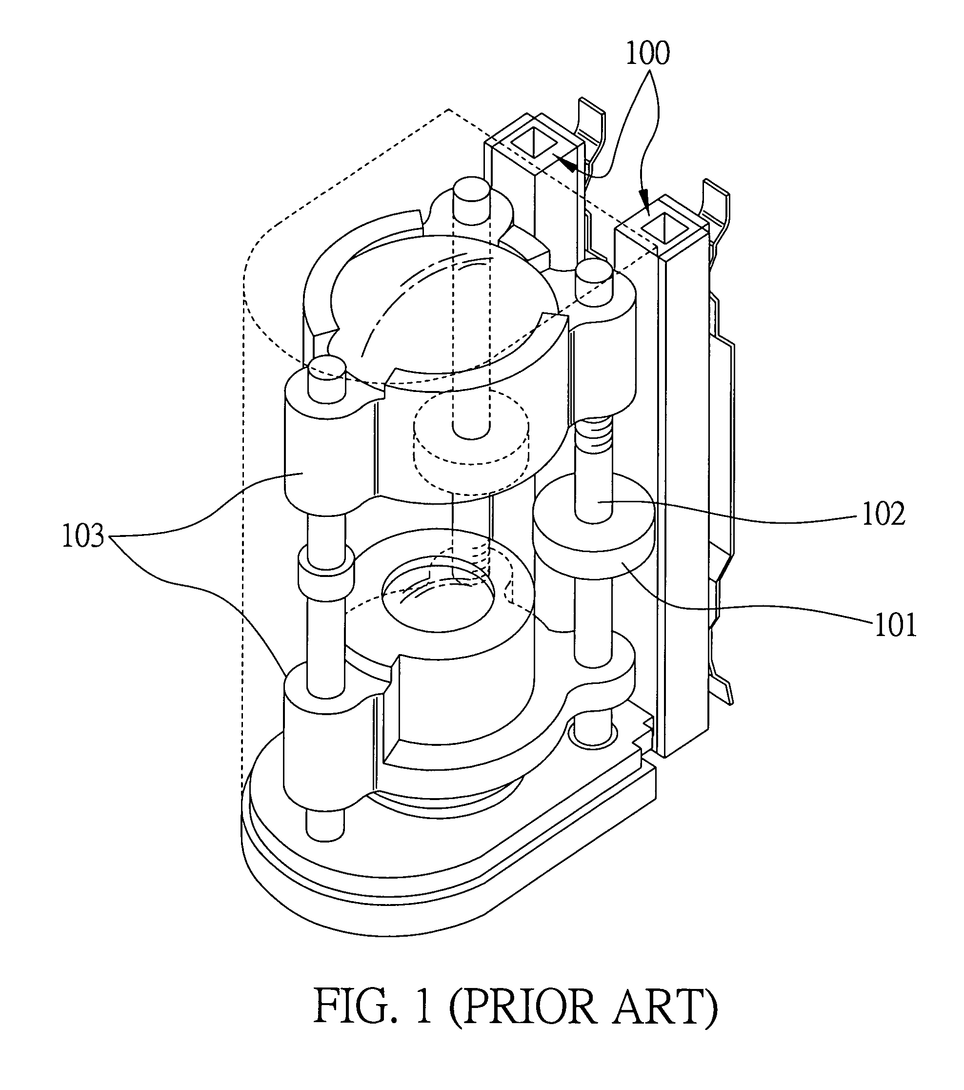
However, it requires the driving units 100 to output more force, thereby consuming more power and decreasing overall driving efficiency; on the other hand, enlarging the contact wheel 101 increases the overall volume of the compact lens module to the detriment of miniaturization.
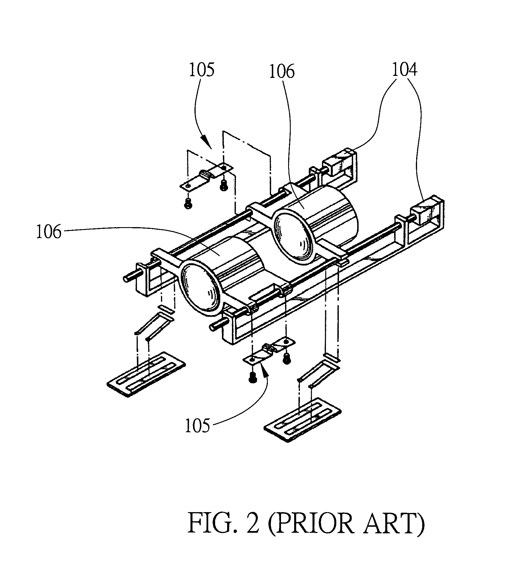
However, the piezoelectric element 104 has to be implemented in the form of a multi-layered piezoelectric disk to perform sufficient displacement and generate sufficient output force, and therefore, it is difficult to thin out the laminated piezoelectric element 104.
However, a plurality of piezoelectric elements is used in the patent, thereby incurring high costs and causing difficulty in assembly.
Moreover, it is very difficult to control precision of displacements, while driving each of the piezoelectric elements to simultaneously poke the lens element.
This is detrimental to miniaturization.
This does not only increase the overall external diameter of the driving device and difficulty in assembly, but also increases the overall weight of the driving device.

Method used


Image

  • Piezoelectrically driven optical lens module
  • Piezoelectrically driven optical lens module
  • Piezoelectrically driven optical lens module

Examples


first embodiment

[0033]Referring to FIGS. 5, 6A and 6B, the present invention provides a piezoelectrically driven optical lens module, comprising: a lens body 2, at least a piezoelectric element 3 for providing driving force, at least a rod 4 in contact with the piezoelectric element 3 to provide an axial movement track, and at least an elastic element 5 for providing the piezoelectric element 3 with pre-load to contact the guiding rod 4. The above-mentioned constituent elements are sufficient to constitute a modularized piezoelectrically driven optical lens module. Due to various degrees of modularization, the piezoelectrically driven optical lens module may further integrate a position detection device 6 for detecting changes in position or an image sensor 7 for capturing images. The variations depend on specifications of actual product assemblies. Both of the position detection device 6 and image sensor 7 are illustrated herein with the appended drawings to enhance comprehension of the present in...

second embodiment

[0050]Referring to FIGS. 7 and 8, the present embodiment is different from the first embodiment in the position of disposal of an enclosed hollow structure 21′, a plurality of lens barrels 22′ and a plurality of lens elements 23′ of a lens body 2′. The position detection device 6 is present in the first embodiment but absent from the second embodiment. Since the design of other related elements, such as the piezoelectric element 3, the guiding rod 4, and the elastic element 5, are mostly the same as those taught in the first embodiment, the same features and reference numerals will not be described repeatedly or redefined. The differences between the first and the present embodiments are described below.

[0051]As shown in FIGS. 7 and 8, the lens body 2′ at least comprises an enclosed hollow structure 21′ having a light aperture 211′ formed therein by external communication, a lens barrel 22′ fixed to the enclosed hollow structure 21′ and axially moveable along the axis of the light a...


PUM


Abstract

The present invention provides a piezoelectrically driven optical lens module. The piezoelectrically driven optical lens module includes at least a lens body, a guiding rod for providing an axial movement track, a piezoelectric element for providing driving force, and an elastic element for providing the piezoelectric element with pre-load, so as to allow the piezoelectric element to be in contact with the guiding rod. The lens body includes at least an enclosed hollow structure, a lens barrel axially moveable and fixed to the enclosed hollow structure, and a lens element fixed to the lens barrel. The piezoelectric element is in contact with the guiding rod via the elastic elements, and the piezoelectric element is used for driving the lens barrel to move linearly along the guiding rod. The present invention provides a piezoelectrically driven optical lens module with a simple structure, to overcome the drawbacks of the prior art.

Description

BACKGROUND OF THE INVENTION[0001]1. Field of the Invention[0002]This invention generally relates to optical lens modules, and more specifically, to a piezoelectrically driven optical lens module.[0003]2. Description of Related Art[0004]In order to cope with the trends toward small-sized cellular phones and cameras, optical systems and their actuators applied to cellular phones and cameras nowadays tend to have a simple structure and a small size. A piezoelectric actuator, which has advantageous features of small size, high output force, low power consumption, noiselessness, and high compatibility, has been widely applied to digital cameras and camera phones, for driving an optical lens module to zoom in or out, and has also become one of the important techniques applied to optical systems or related merchandises.[0005]Taiwanese Patent No. 589,777 discloses a multi-layered, thin-disk, piezoelectrically driven ultrasonic motor, which is characterized by applying high AC voltages to pi...

Claims


Application Information

Patent Timeline
Patent Type & Authority Patents(United States)
IPC IPC(8): G02B7/02G03B17/00G03B3/10
CPCG02B7/102
Inventor HU, CHAO-CHANGSU, HAN-WEICHEN, CHING-CHANG
Owner IND TECH RES INST
Learn More