Eureka AIR delivers breakthrough ideas for toughest innovation challenges, trusted by R&D personnel around the world.

Hydraulic damper integrated into steering rack for attenuating steering nibble

a damper and hydraulic technology, applied in the direction of springs/dampers, rigid suspensions, power driven steering, etc., can solve the problems of chassis mode energy dissipation, steering nibble is significant, steering oscillation, etc., to reduce the volume of the second working chamber, increase the volume of the working chamber, and reduce the volume of the chamber

Inactive Publication Date: 2009-02-03
IQ ISOLATION QUALITY
View PDF22 Cites 12 Cited by
  • Summary
  • Abstract
  • Description
  • Claims
  • Application Information

AI Technical Summary

Benefits of technology

[0008]The present invention provides a variety of designs for damping systems for use with a variety of mechanisms or systems that require damping. A first preferred embodiment of the present invention provides a damping system for use with a steering system of the type having a steering gear and a tie rod which moves toward and away from the steering gear to cause movement of a vehicle wheel. The damping system includes a boot defining a working chamber. The boot has a first portion connected to the steering gear and a second portion connected to the tie rod such that movement of the tie rod toward the steering gear reduces the volume of the working chamber and movement of the tie rod away from the steering gear increases the volume of the working chamber. An inertia track has a first end in fluid communication with the working chamber of the boot and an opposed second end. A collection chamber is in fluid communication with the second end of the inertia track. A fluid is disposed in the working chamber, the inertia track, and at least a portion of the collection chamber. A compliant tuning member is in fluid communication with the working chamber. The tuning member is movable to accommodate high frequency changes in the volume of the working chamber.
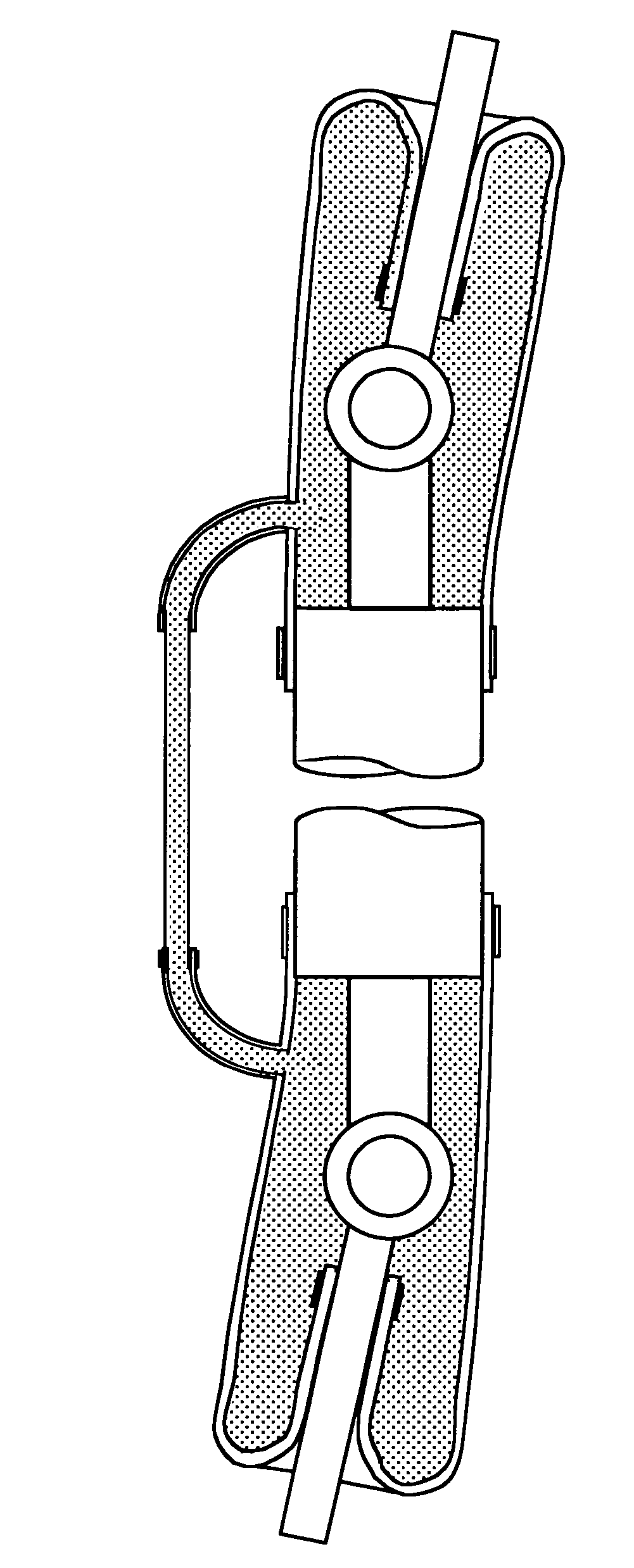
[0010]In further versions of the first embodiment, the steering gear is of the type further having a second tie rod which moves towards and away from the steering gear. The system further includes a second boot defining a second working chamber. The second boot has a first portion connected to the steering gear and a second portion connected to the second tie rod such that movement of the tie rod toward the steering gear reduces the volume of the second working chamber and movement of the tie rod away from the steering gear increases the volume of the working chamber. The second end of the inertia track is in fluid communication with the second boot such that the second boot forms the collection chamber. Alternatively, in a system including a second boot, a second inertia track and a second collection chamber may be provided, along with a second compliant tuning member. The inertia tracks may have the same cross-sectional area in length, or the area and / or lengths may be different from each other.
[0011]According to a further embodiment of the present invention, a damping system is provided for use with a steering system of the type having a steering gear and a tie rod which moves toward and away from the steering gear to cause movement of a vehicle wheel. The damping system is tuned to at least partially damp a chosen frequency. The system includes a variable volume chamber in mechanical communication with the steering gear and the tie rods such that movement of the tie rod in a first direction with respect to the steering gear reduces the volume of the chamber and movement of the tie rod in a second direction with respect to the steering gear increases the volume of the chamber. The system further includes a collection chamber and an inertia track having one end in fluid communication with the variable volume chamber and an opposed second end in fluid communication with the collection chamber. A fluid is disposed in the variable volume chamber, the inertia track and at least a portion of the collection chamber. A compliant tuning member is in fluid communication with the chamber. The cross-sectional area and length of the inertia track and the deflection stiffness of the compliant tuning member are chosen such that the system damps movement of the tie rod relative to the steering gear generally at the chosen frequency.
[0012]According to yet a further embodiment of the present invention, a damping system is provided for use with a mechanism having a first element which moves toward and away from a second element. The damping system is tuned to at least partially damp a chosen frequency. The system includes a variable volume chamber in mechanical communication with the mechanism such that movement of the first element in a first direction with respect to the second element reduces the volume of the chamber and movement of the first element in a second direction with respect to the second element increases the volume of the chamber. The system further includes a collection chamber and an inertia track having a first end in fluid communication with the variable volume chamber and an opposed second end in fluid communication with the collection chamber. A fluid is disposed in the variable volume chamber, the inertia track and at least a portion of the collection chamber. A volume of fluid is displaced into or from the variable volume chamber by movement of the first element relative to the second element. The volume displaced per unit of movement is defined as dV / dx. An actual fluid mass for the inertia track is given by the formula: actual fluid mass=(cross-sectional area)×(length)×fluid density. The system has an effective mass given by the formula: system effective mass=((dV / dx) / (cross-sectional area))2×actual fluid mass. A compliant tuning member is in fluid communication with the chamber. The compliant tuning member has a deflection stiffness and an area. The system has a system effective stiffness given by the formula: system effective stiffness=((dV / dx) / (area of compliant member))2×deflection stiffness. The system has a resonant frequency given by the formula: system resonant frequency=(system effective stiffness / system effective mass)1 / 2. The cross-sectional area in length of the inertia track and the deflection stiffness of the compliant tuning member are chosen such that the system resonant frequency is generally at the chosen frequency. Some versions of this embodiment are designed for use with a steering system, wherein the first element is a tie rod and the second element is a steering rack. The system may further include a boot that defines the variable volume chamber, with the boot having a first portion connected to the steering rack and a second portion connected to the tie rod. The boot may be a rolling boot. In some versions, the system effective mass is at least 100 times the actual fluid mass, and in further versions the system effective mass is at least 200 times the actual fluid mass. The system resonant frequency may be in the range of 10-25 hertz.

Problems solved by technology

Chassis modes can cause vibration to propagate through the steering gear and result in oscillations of the steering wheel, also referred to as “steering nibble”.
Steering nibble is a significant issue for the automotive industry.
This arrangement provides some chassis mode energy dissipation; however, the attenuation may be insufficient because frictional damping becomes less effective at higher frequencies.
Therefore, any arrangement that relies on increased frictional damping to control 10-15 Hz vibrations will negatively impact steering feel.
Increased damping at low frequencies degrades steering feel, while increased damping at high frequencies transmits more vibration into the passenger compartment.
The viscous damper provides this compromised performance as well as a significant cost increase.

Method used


Image

  • Hydraulic damper integrated into steering rack for attenuating steering nibble
  • Hydraulic damper integrated into steering rack for attenuating steering nibble
  • Hydraulic damper integrated into steering rack for attenuating steering nibble

Examples


Embodiment Construction

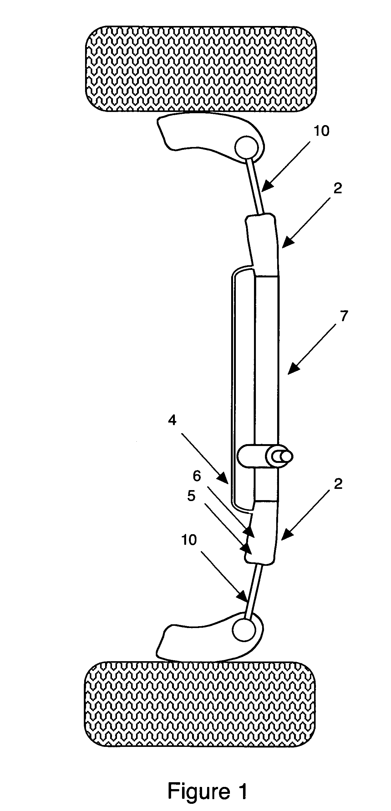
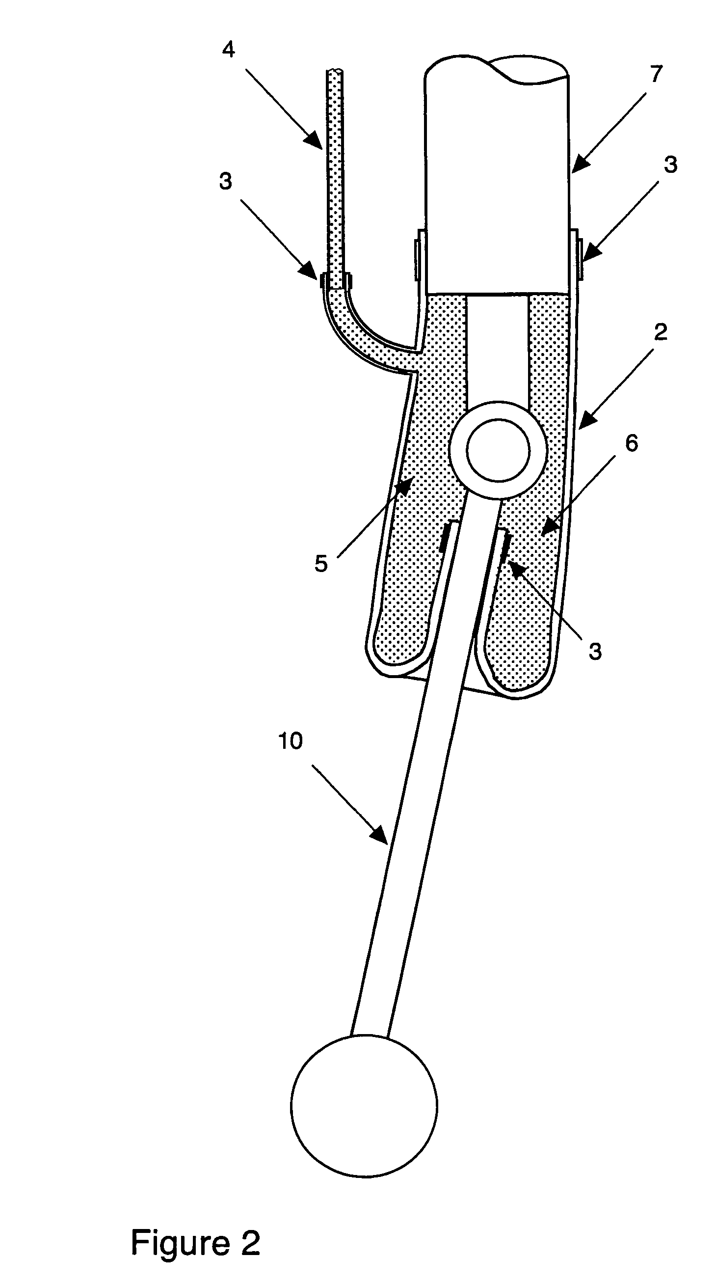
[0031]A modified vehicle steering suspension arrangement is shown schematically in FIG. 1. This steering arrangement includes a hydraulically tuned steering damping system, which is comprised of two rolling boots 2 connected by an inertia track 4 and filled with working fluid 6. The hydraulically tuned steering damping system, and the new rolling boots 2 in particular, are shown in greater detail in FIG. 2.

[0032]The two rolling boots 2 replace the common dust boots found on steering gears, whose function was to prevent dirt from entering the steering gear 7. The inertia track 4 may replace the common air equalization tube found on steering gears, whose function is to prevent the air trapped with the dust boots from building up pressure.

[0033]The hydraulically tuned steering damping system works on some similar principles as existing hydromounts, however, it is designed to accommodate much greater displacements than hydromounts and does not add significant static stiffness to the sys...


PUM


Abstract

The present invention provides a damping system for use with a mechanism such as a steering system wherein one element moves relative to another element. The system includes a variable volume chamber, a collection chamber, and an inertia track providing fluid communication between the two chambers. A fluid is disposed in the chambers and the inertia track. A compliant tuning member is in fluid communication with the variable volume chamber. The damping system is capable of attenuating vibration at chosen frequencies without adding undesired damping at other frequencies. In the preferred embodiment, the damping system is used to attenuate steering wheel torsional vibration without increasing low frequency damping that would deteriorate steering feel.

Description

REFERENCE TO RELATED APPLICATIONS[0001]This application is a continuation-in-part of U.S. patent application Ser. No. 10 / 649,605, filed Aug. 28, 2003, which claims priority to U.S. Provisional Patent Application Ser. No. 60 / 480,219, filed Jun. 30, 2003. This application also claims priority to U.S. Provisional Patent Application Ser. No. 60 / 630,160, filed Nov. 23, 2004, the entire content of all of which are incorporated herein.FIELD OF THE INVENTION[0002]The present invention relates to steering arrangements and in particular to steering arrangements, which can provide tuned damping capable of handling large displacements.BACKGROUND OF THE INVENTION[0003]Existing vehicle wheel steering arrangements include a steering gear, tie rods, control arms, control arm bushings, and wheels. The frictional damping within the steering gear affects both steering feel, which is generally at frequencies less than 2 Hz, and the higher frequency chassis modes, which are typically in the range of 10-...

Claims


Application Information

Patent Timeline
Patent Type & Authority Patents(United States)
IPC IPC(8): B62D7/22B60G1/00B60G17/04B60G17/08F16F9/06F16F9/504
CPCB60G17/04B60G17/08B62D7/22B62D7/228F16F9/06F16F9/16F16F9/504F16J3/041F16F2230/105
Inventor GORODISHER, ALEXANDER VLADIMIRBOUGHTON, MORRIS W.DREFF, FIMA
Owner IQ ISOLATION QUALITY
Why Eureka
Eureka Blog
Learn More