Supercharge Your Innovation With Domain-Expert AI Agents!

Light source apparatus and image display apparatus

a technology of light source and image display, which is applied in the field of light source apparatus and image display apparatus, can solve the problems of difficult to increase the light intensity and unsuitable high-intensity light source, and achieve the effect of reducing the loss of light amoun

Inactive Publication Date: 2009-02-03
CANON KK
View PDF3 Cites 0 Cited by
  • Summary
  • Abstract
  • Description
  • Claims
  • Application Information

AI Technical Summary

Benefits of technology

This configuration enhances light usage efficiency, allowing for a higher number of light-emitting elements to be used, resulting in a compact, bright, and evenly illuminated image display with reduced luminance and color unevenness.

Problems solved by technology

Such a side-face LED placement is effective for thinning flat light source apparatuses, but unsuitable for high-intensity light sources since many LEDs cannot be placed on the side face.
Accordingly, using a common polarizer for obtaining linearly polarized light reduces the amount of light from the LEDs and therefore it is difficult to increase the light intensity without changing the number of LEDs or with reduction thereof.

Method used


Image

  • Light source apparatus and image display apparatus
  • Light source apparatus and image display apparatus
  • Light source apparatus and image display apparatus

Examples


Embodiment Construction

[0024]Preferred embodiments of the present invention will hereinafter be described with reference to the drawings.

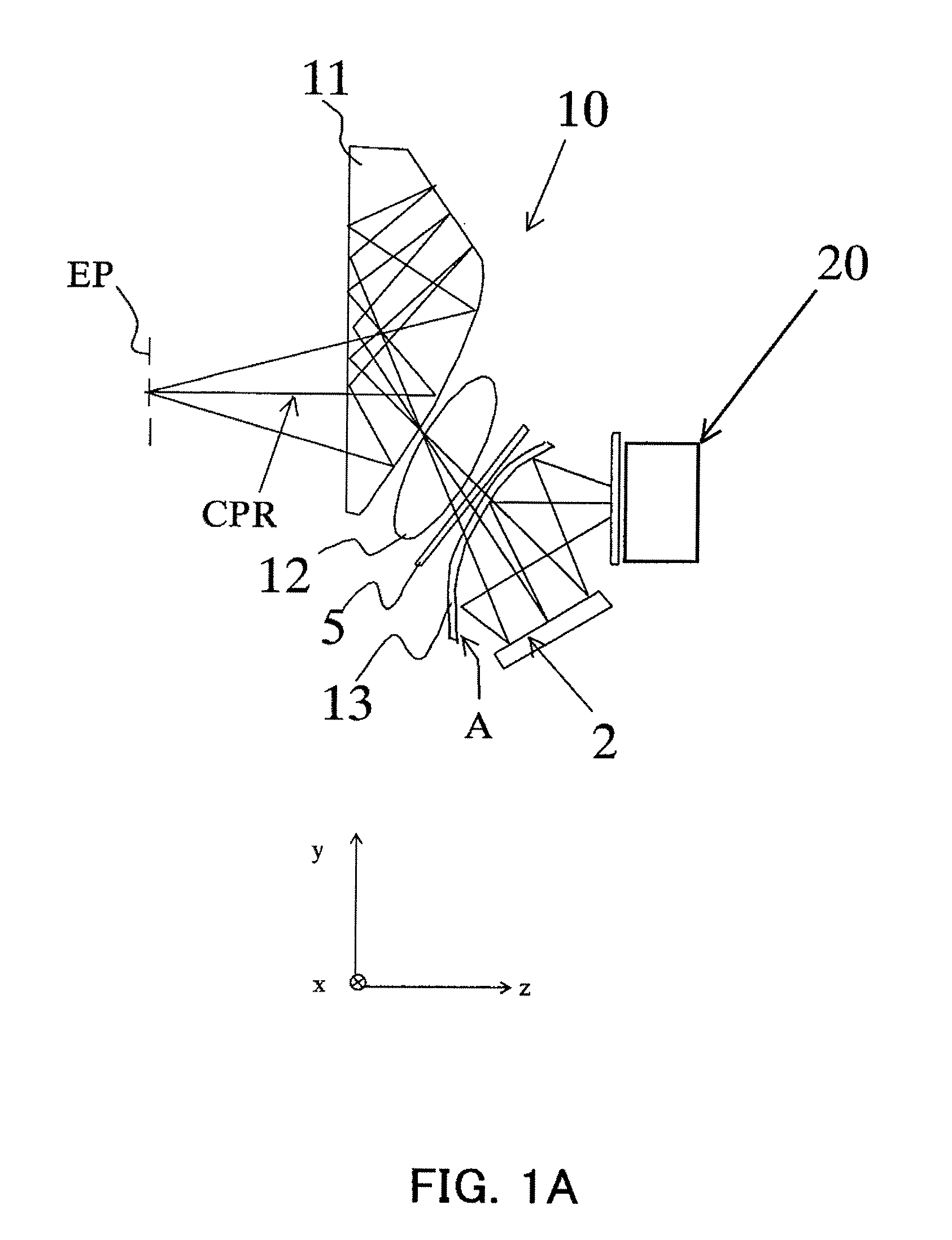
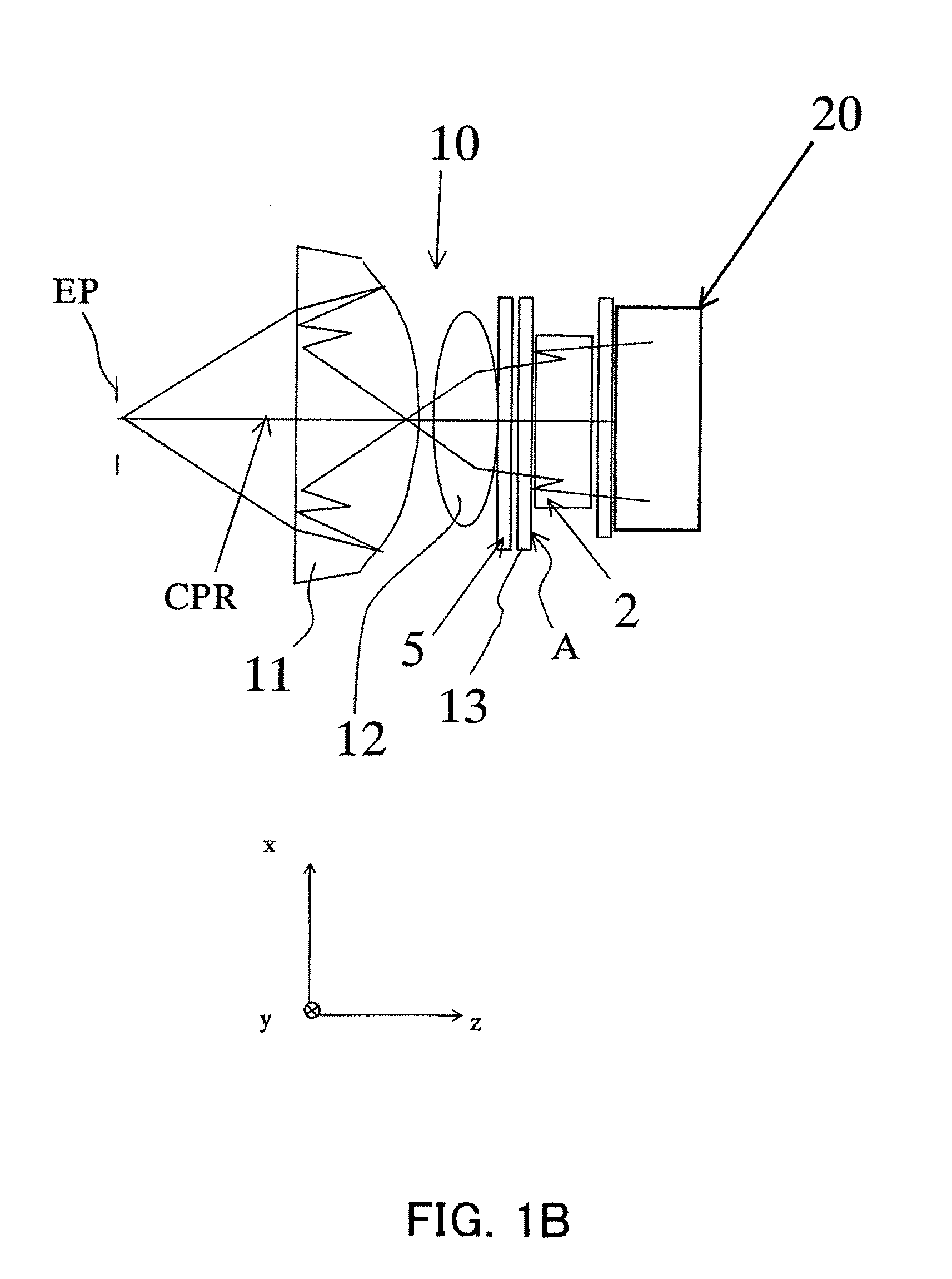
[0025]FIGS. 1A and 1B show the basic configuration of the HMD (image display apparatus) that is an embodiment of the present invention. In FIGS. 1A and 1B, 11 denotes a prism, and 12 a lens. 5 denotes a polarizing plate that is an analyzer, and 13 a lens including a semi-transmissive / reflective surface A and having optical power (that is, the inverse of the focal length) in the yz cross section. These prism 11, lens 12, polarizing plate 5 and lens 13 constitute a displaying optical system 10.

[0026]2 denotes a reflective liquid crystal panel. 20 denotes a light source unit that is a light source apparatus. The light source unit 20 converts light from LEDs, which are plural light-emitting elements and described later, into linearly polarized light with a predetermined polarization direction (or, a first polarization direction) and causes it to emerge.

[0027]FIG. 1A shows th...


PUM


Abstract

A light source apparatus is disclosed which is capable of emerging predetermined linearly polarized light while a loss of light amount is reduced. The light source apparatus comprises plural light-emitting elements which are disposed so that their light-emitting surfaces face the direction of an emergence surface of the light source apparatus, and a polarization selective element which transmits a light component with a first polarization direction and reflects a light component with a second polarization direction different from the first polarization direction. The apparatus further comprises a reflecting surface which is disposed at a position closer to the light-emitting elements than the polarization selective element and reflects the reflected light from the polarization selective element to the polarization-selective element side.

Description

BACKGROUND OF THE INVENTION[0001]The present invention relates to light source apparatuses, which are used in image display apparatuses such as head mounted displays (HMDs) and illuminate image-forming elements such as reflective liquid crystal panels.[0002]Conventional HMDs, which includes a transmissive liquid crystal panel with color filters, use a cold-cathode-tube type white flat light source to illuminate the liquid crystal panel.[0003]In contrast, many recent HMDs use a light source capable of emitting light of three (RGB) colors and adopt a color-sequential displaying method in which images on the liquid crystal panel are rewrite in accordance with a light-emission switching timing of the light source.[0004]Moreover, color LEDs are often used as a light source of HMDs. The color LED has three light-emitting portions of RGB, and the emission color and emission intensity of the LED can be electrically controlled.[0005]In such light source apparatuses, two to four LEDs are ofte...

Claims


Application Information

Patent Timeline
Patent Type & Authority Patents(United States)
IPC IPC(8): F21S8/00
CPCG02B27/0172G02B5/30G02B2027/0118
Inventor YAMAZAKI, SHOICHIINOGUCHI, KAZUTAKA
Owner CANON KK
Features
  • R&D
  • Intellectual Property
  • Life Sciences
  • Materials
  • Tech Scout
  • Unparalleled Data Quality
  • Higher Quality Content
  • 60% Fewer Hallucinations
Learn More