
Optical transmission apparatus and method

a transmission apparatus and optical technology, applied in the field of optical transmission apparatus and method, can solve the problems of difficult use of wdm light source, insufficient output power to provide plurality, and high cost of dfb ld

Inactive Publication Date: 2009-02-03
ELECTRONICS & TELECOMM RES INST
View PDF14 Cites 0 Cited by
  • Summary
  • Abstract
  • Description
  • Claims
  • Application Information

AI Technical Summary

Benefits of technology

This solution provides an economical and efficient method for generating multiple channels with stable wavelengths, reducing interference and chromatic dispersion, and enabling cost-effective WDM optical communication systems by using a Fabry-Perot laser diode with incoherent light sources, enhancing the optical signal-to-noise ratio and accommodating multiple users with different wavelengths.

Problems solved by technology

However, since the DFB LD is expensive, incoherent lights are usually used in the access network that requries an economical light source.
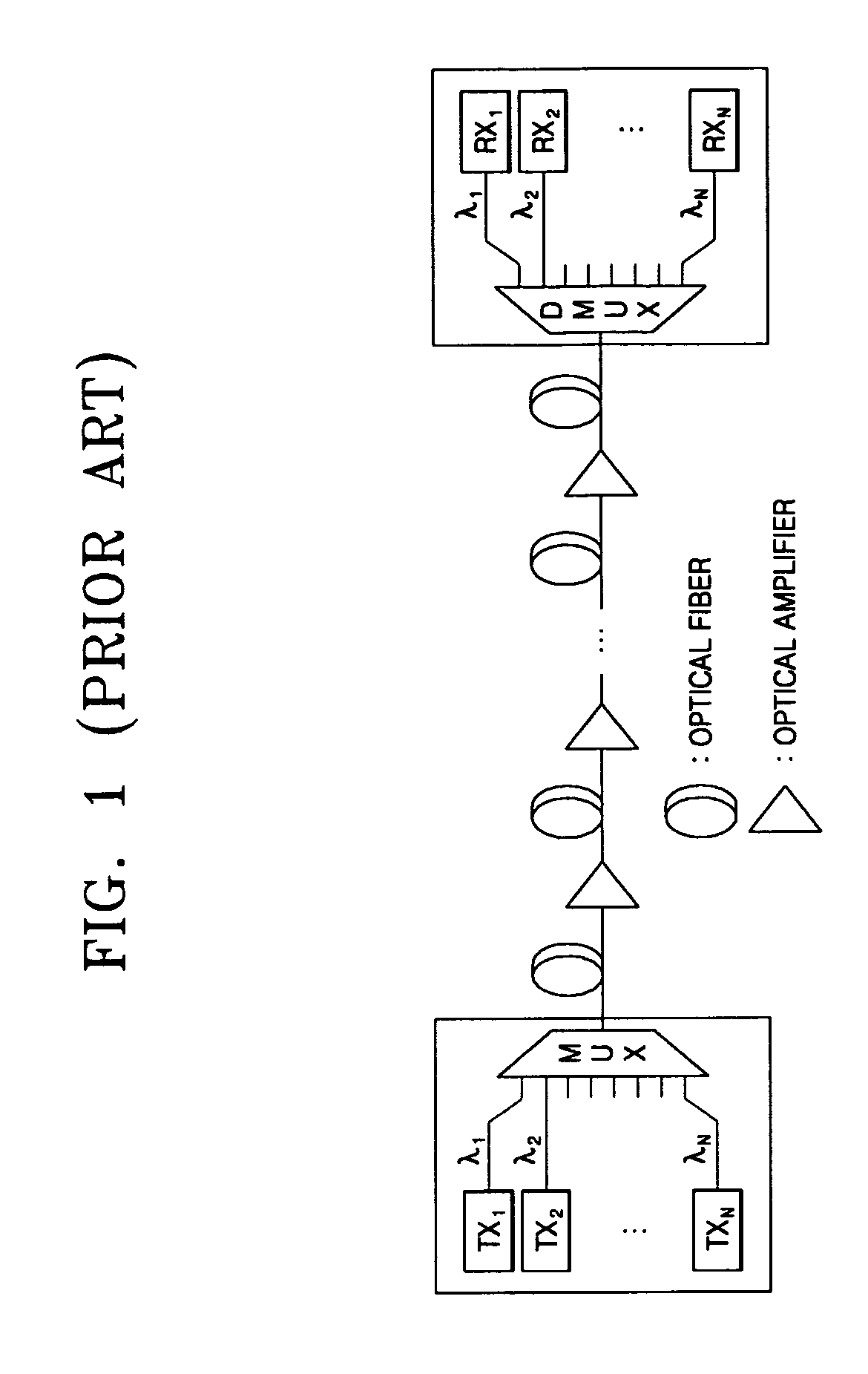
Since incoherent lights using a light emitting diode (LED), a super luminescent diode (SLD), and a natural emitting light of the optical amplifier have wide spectrums, it is difficult to use a WDM light source as it is, and a spectrum slicing method is used.
However, the LED does not have sufficient output power to provide a plurality of channels using the spectrum slicing method, and while the SLD has relatively high output power it is expensive.

Method used


Image

  • Optical transmission apparatus and method
  • Optical transmission apparatus and method
  • Optical transmission apparatus and method

Examples


Embodiment Construction

[0030]The present invention will now be described more fully with reference to the accompanying drawings, in which exemplary embodiments of the invention are shown.

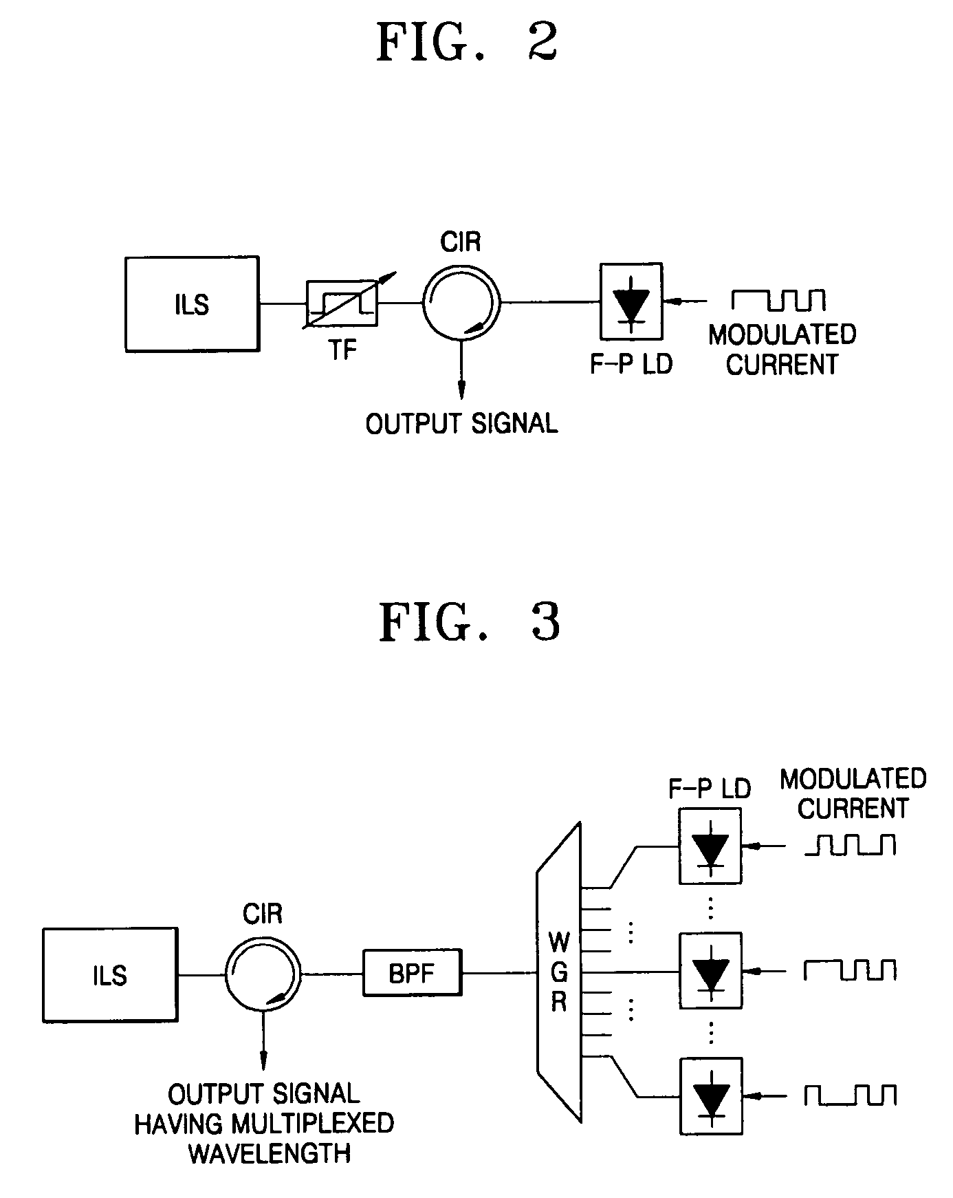
[0031]FIG. 2 illustrates a constitution of a light source using a Fabry-Perot laser diode (F-P LD) whose output wavelength is locked by an externally injected incoherent light. The light source includes an incoherent light source (ILS), a tunable filter (TF) that passes a component of a desired wavelength band among output lights of the ILS and tunes a pass band, the F-P LD, and a circulator (CIR) that transfers an output of the TF to the F-P LD and outputs light input from the F-P LD.

[0032]The ILS uses an optical fiber amplifier that outputs a natural emitting light, a light emitting diode (LED), and a super luminescent diode (SLD). An isolator is removed from the F-P LD so as to inject a light from outside.

[0033]An operation of the light source will now be described.

[0034]A component of a filter pass band among output l...


PUM


Abstract

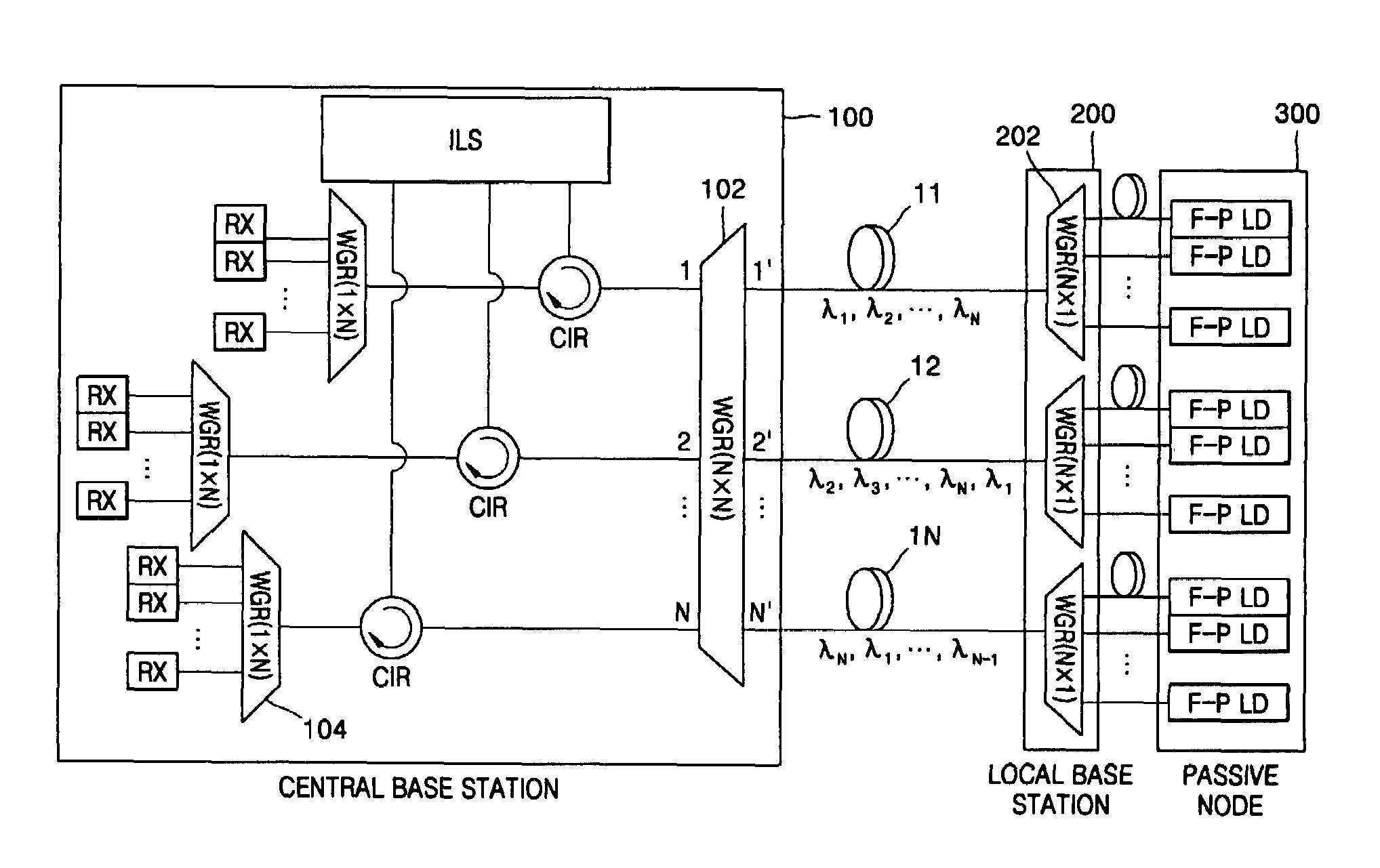
Provided are an optical transmission apparatus and method using a light source for wavelength division multiplexing (WDM) optical communication that employs a Fabry-Perot laser diode (F-P LD) whose output wavelength is locked by an externally injected incoherent light, a multifiber, and a waveguide grating router. The light transmission apparatus includes: an incoherent light source (ILS) outputting incoherent light; a plurality of circulators (CIRs) connected to the ILS, receiving the incoherent light from the ILS, and outputting first optical signals; a first waveguide grating router (WGR) outputting the first optical signals output from each of the CIRs to optical fibers corresponding to each of the CIRs, and outputting second optical signals input from the optical fibers to the corresponding CIRs; a plurality of second WGRs corresponding to each of the CIRs, and demodulating the second optical signals output from each of the plurality of CIRs; and a plurality of receivers connected to the plurality of the second WGRs, and inputting the demultiplexed optical signals output from the plurality of second WGRs. A plurality of light sources for WDM optical communication whose output wavelength is locked can increase size and economical efficiency of a light transmission system (subscriber). The N×N WGR can produce a conventional light transmission system and accommodate many subscribers.

Description

BACKGROUND OF THE INVENTION[0001]This application claims the benefit of Korean Patent Application No. 10-2004-0102964, filed on Dec. 8, 2004, and Korean Patent Application No. 10-2005-0042423, filed on May 20, 2005, in the Korean Intellectual Property Office, the disclosures of which are incorporated herein in their entirety by reference.[0002]1. Field of the Invention[0003]The present invention relates to an optical transmission apparatus and method, and more particularly, to an optical transmission apparatus and method using a light source for wavelength division multiplexing (WDM) optical communication that employs a Fabry-Perot laser diode (F-P LD) whose output wavelength is locked by an externally injected incoherent light, a multifiber, and a waveguide grating router.[0004]2. Description of the Related Art[0005]Wavelength division multiplexing (WDM) optical transmission apparatuses are being introduced to satisfy increasing communication demands. In particular, WDM optical tra...

Claims


Application Information

Patent Timeline
Patent Type & Authority Patents(United States)
IPC IPC(8): H04J14/00H04B10/2581
CPCH04B10/40H04J14/0227H04J14/0282H04J14/0246H04J14/025H04J14/0226H04B10/2581H04B10/25
Inventor LEE, HYUN JAEKIM, KWANG JOON
Owner ELECTRONICS & TELECOMM RES INST
Learn More