Tire parameter monitoring system with sensor location using magnetic fields

a technology of magnetic field and tire parameter, which is applied in the direction of tire measurement, vehicle components, transportation and packaging, etc., can solve the problems of system re-correlation, required installation of separate interrogation antennae adjacent to tire parameter sensor units, and inability to detect the position of the tire parameter sensor unit, etc., to achieve simple and inexpensive implementation, high reliability

Inactive Publication Date: 2009-02-10
SILICON VALLEY MICRO C
View PDF8 Cites 10 Cited by
  • Summary
  • Abstract
  • Description
  • Claims
  • Application Information

AI Technical Summary

Benefits of technology

[0011]The invention comprises a method and system for providing sensor unit location information which is simple and inexpensive to implement, highly reliable, and accurate.

Problems solved by technology

A disadvantage with this type of location correlation technique is that any change to the original tire and sensor unit location requires that the system be re-correlated.
While some vehicle owners may be capable of acquiring the necessary skill and training, others may not.
The latter will necessarily suffer delay and expense when re-configuring the vehicle tires and wheels; the former will suffer at least the delay attendant upon re-familiarizing oneself with the steps required to re-program an electronic system.
A disadvantage to the interrogator antenna system described above lies in the requirement for the installation of the separate interrogation antennae adjacent the tire parameter sensor units.
As a consequence, installation cost and hardware durability are factors of concern when deciding to implement such a system.
Efforts to provide a simple, inexpensive, reliable, and accurate sensor unit location feature for a tire parameter sensing system devoid of the above-noted disadvantages have not been successful to date.

Method used


Image

  • Tire parameter monitoring system with sensor location using magnetic fields
  • Tire parameter monitoring system with sensor location using magnetic fields
  • Tire parameter monitoring system with sensor location using magnetic fields

Examples


Embodiment Construction

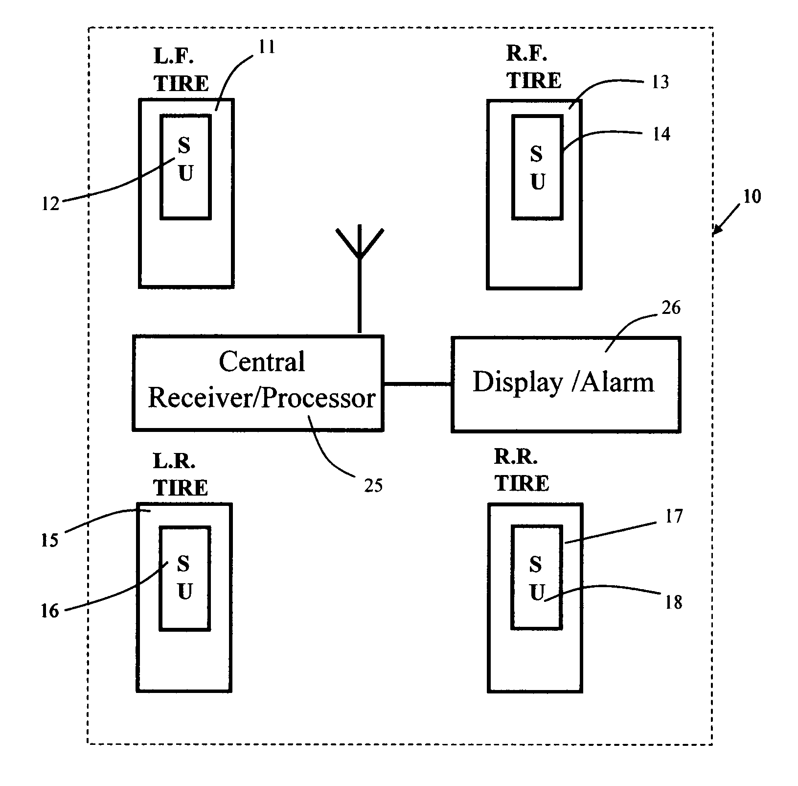
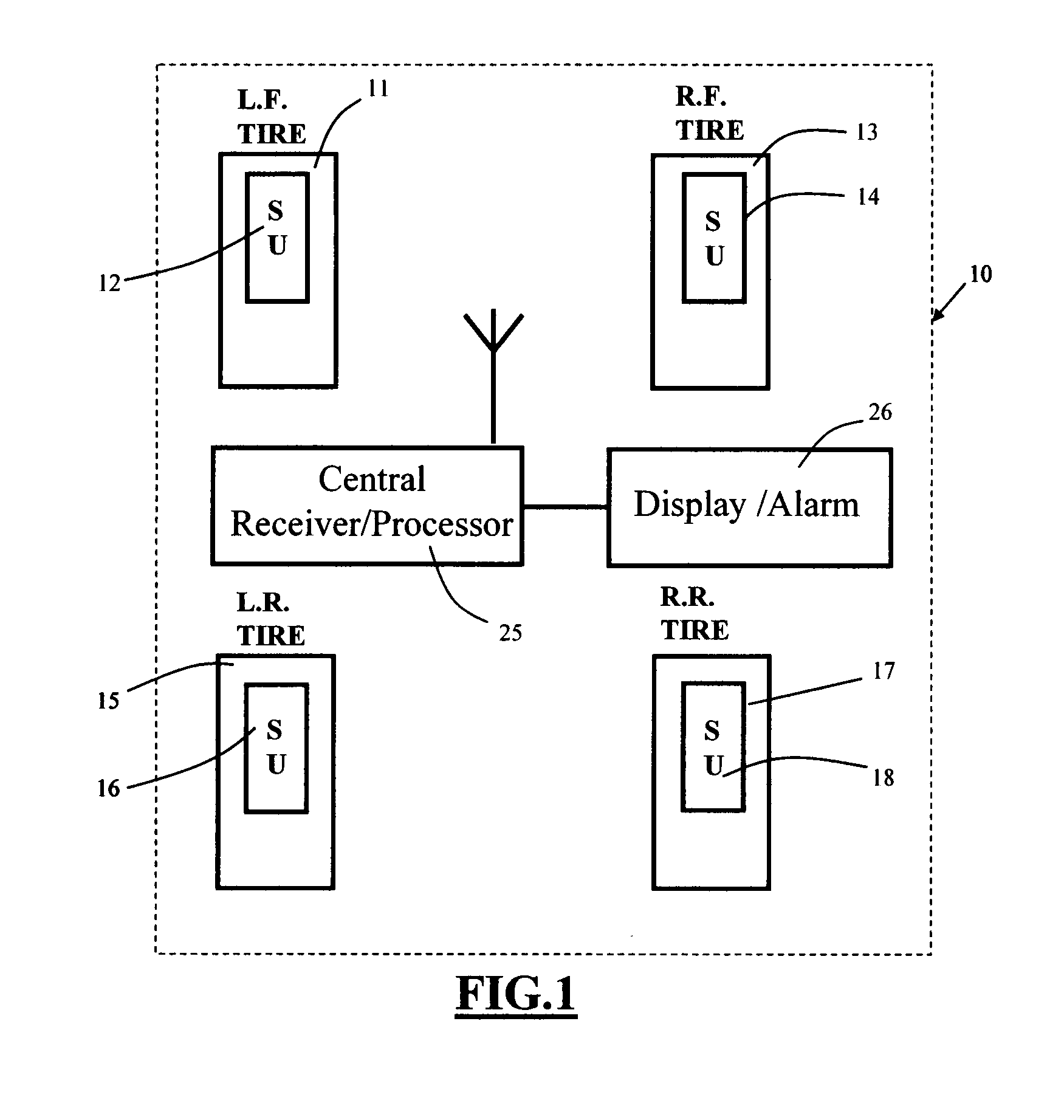
[0037]Turning now to the drawings, FIG. 1 is a schematic top plan view of a tire parameter sensing system incorporating the sensor unit location feature of the invention. As seen in this Fig., which illustrates a vehicle having four tires and wheels, each tire has an associated tire parameter sensor unit SU. Thus, left front tire 11 is provided with SU 12; right front tire 13 is provided with SU 14; left rear tire 15 is provided with SU 16; and right rear tire 17 is provided with SU 18. As described more fully below in connection with FIG. 6, each SU 12, 14, 16, and 18 is connected to one or more tire parameter sensors for monitoring the state of individual tire parameters, such as internal tire pressure, tire temperature, internal tire air temperature, and lateral tire force. Such sensors are well known in the art and will not be described further to avoid prolixity. The physical location of the individual SUs 12, 14, 16, and 18 is a matter of design choice and may include the oute...


PUM


Abstract

A tire parameter monitoring system has a plurality of sensor units each mounted with a different vehicle tire. Each sensor unit has a magnetic sensing element for converting magnetic field signals generated by a proximate set of magnets mounted to the vehicle at the tire locations. Each magnet set generates a unique magnetic field which identifies the magnet set location. Each sensor unit has a microcontroller for combining the converted magnetic field signals with fire parameter signals, and a transmitter for transmitting the combined signals to a receiving location. Received tire parameter signals are correlated with the tire location using the location signals, and driver advisory signals are presented to the driver.

Description

BACKGROUND OF THE INVENTION[0001]This invention relates to vehicle tire parameter monitoring systems. More particularly, this invention relates to a fire parameter monitoring system having a sensor unit position location feature using permanent magnets.[0002]Tire parameter monitoring systems are known and are commonly used to monitor one or more parameters of interest in individual pneumatic tires of a vehicle and to provide an advisory signal to the driver, usually via an on-board computer system, containing information about the fire parameter(s). The portion of the fire parameter monitoring system located at or in the individual fires is termed the sensor unit, and is coupled to one or more sensors capable of measuring the parameter(s) of interest and generating an electrical signal representative of the value of the measurement, a signal generator (typically an r.f. signal generator) capable of generating a wireless signal corresponding to the electrical signal, a microcontrolle...

Claims


Application Information

Patent Timeline
Patent Type & Authority Patents(United States)
IPC IPC(8): B60C23/02
CPCB60C23/0416
Inventor ZHU, SHENGBOHUARG, SU SHIONG
Owner SILICON VALLEY MICRO C
Why Eureka
Try Eureka