Eureka AIR delivers breakthrough ideas for toughest innovation challenges, trusted by R&D personnel around the world.

Sterile de-molding apparatus and method

a container and de-molding technology, applied in the direction of liquid handling, packaging, packaging goods, etc., can solve the problems of more defectively filled containers than otherwise desired, time-consuming filling process, and high cost of processes and equipment, so as to maintain the sterility of the container

Inactive Publication Date: 2009-02-17
MEDINSTILL DEV
View PDF43 Cites 9 Cited by
  • Summary
  • Abstract
  • Description
  • Claims
  • Application Information

AI Technical Summary

Benefits of technology

[0027]One advantage of the present invention is that the container bodies and stoppers are sterile at the time of formation due to the heat of the molten plastic used to form the parts, the introduction of the molten plastic into the mold cavity spaces thermally sterilizes the surfaces that contacts the plastic, or at least maintains such surfaces sterile, and thus the surfaces of the container parts are maintained sterile within the mold at the time of formation. Another advantage of the present invention is that when the mold is moved into the open position to allow de-molding of the sterile parts, the mold surfaces extending about the container parts (or mold cavities) are maintained sterile, and the space between the opposing surfaces of the open mold is maintained sterile by the flow of sterile gas therethrough. Yet another advantage is that the flexible barriers further substantially prevent any contaminants from entering the sterile space that otherwise might enter such space from the molding machine or base portion of the tool or related assembly device. A still further advantage is that when the tool engages and de-molds the container parts, the sterile gas flows over the tool and container parts to further maintain their sterility during de-molding. If desired, the tool can be used to assemble the container bodies and stoppers within the aseptic enclosure into sealed, empty sterile containers. Then, the sealed, empty sterile containers can be aseptically needle filled, and laser resealed. Accordingly, the apparatus and method of the invention can obviate the need for an isolator, the need to use gamma radiation to sterilize the container parts, or the need to terminally sterilize the filled containers, thus avoiding the related problems encountered in the prior art.
[0028]Other advantages of the present invention will become more readily apparent in view of the following detailed description of the currently preferred embodiment and accompanying drawings.

Problems solved by technology

One of the drawbacks associated with such prior art container assemblies, and the processes and equipment for filling such container assemblies, is that the filling process is time consuming, and the processes and equipment are expensive.
Further, the relatively complex nature of the filling processes and equipment can lead to more defectively filled containers than otherwise desired.
In many cases, there are complex assembly machines for assembling the containers that are located within the aseptic area of the filling machine that must be maintained sterile.
This type of machinery can be a significant source of unwanted particles.
In closed barrier systems, convection flow is inevitable and thus laminar flow, or substantially laminar flow, cannot be achieved.
When operation of an isolator is stopped, a media fill test may have to be performed which can last for several, if not many days, and can lead to repeated interruptions and significant reductions in production output for the pharmaceutical, nutritional or other product manufacturer that is using the equipment.
In order to address such production issues, government-imposed regulations are becoming increasingly sophisticated and are further increasing the cost of already-expensive isolators and like filling equipment.
On the other hand, governmental price controls and marketplace competition for pharmaceuticals and vaccines, including, for example, preventative medicines, and other aseptically filled products, such as liquid nutrition products, discourage such major fmancial investments.
One of the drawbacks of gamma sterilization is that it can damage or otherwise negatively affect the parts to be sterilized, such as by discoloring parts formed of plastic and other gamma-sensitive materials.
In addition, if used to terminally sterilize filled containers, gamma radiation can damage the product stored within the container.
Accordingly, gamma sterilization has limited applicability, and further, is not always a desirable form of sterilization for many types of products with which it is used.
One of the drawbacks of such prior art filling machines and processes is that the fluid sterilant, such as vaporized hydrogen peroxide, necessarily must contact and sterilize the interior surfaces of the containers.
This, in turn, can lead to peroxidation or the formation of free radicals that can alter or otherwise degrade the product formulation during its shelf life, or otherwise can degrade the taste or other qualities of the product in the container.

Method used


Image

  • Sterile de-molding apparatus and method
  • Sterile de-molding apparatus and method
  • Sterile de-molding apparatus and method

Examples


Embodiment Construction

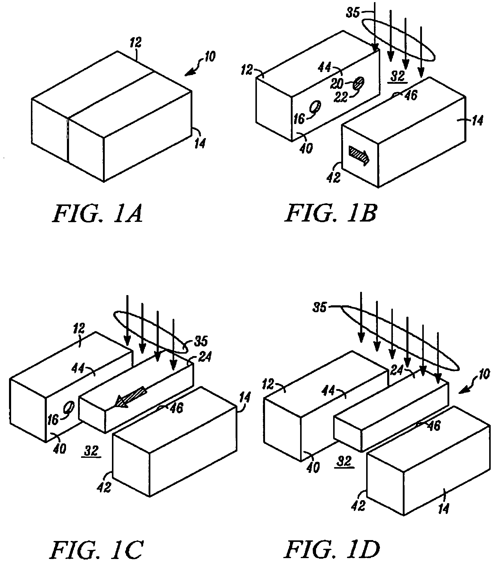
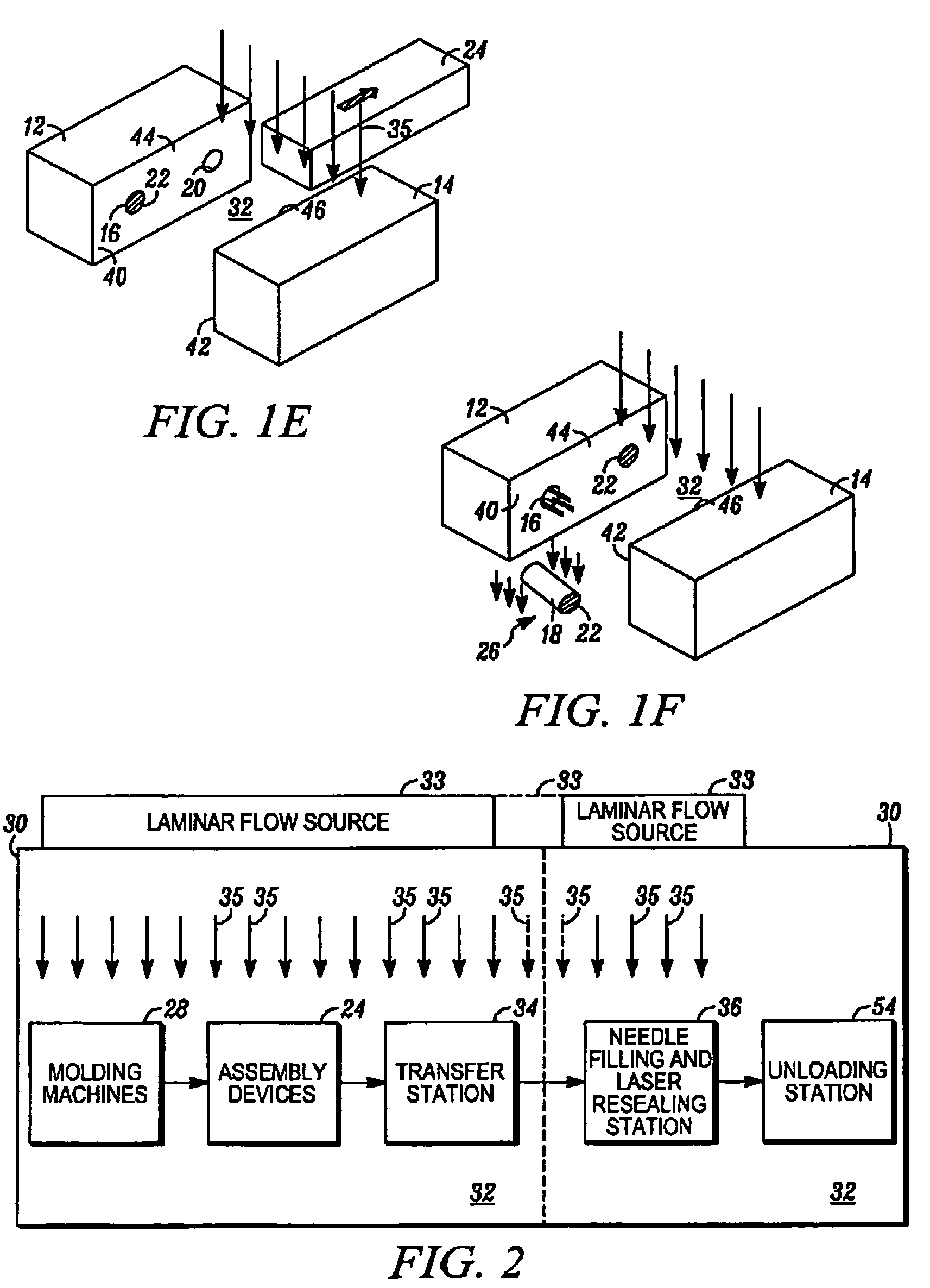
[0034]In FIGS. 1A through 1F, an apparatus embodying the present invention is indicated generally by the reference numeral 10. The apparatus 10 comprises a mold including a first mold half or portion 12, and a second mold half or portion 14. As can be seen, at least one of the first and second mold portions 12 and 14 is movable relative to the other in a manner known to those of ordinary skill in the pertinent art between a closed position for molding the container parts therein, and an open position for de-molding or releasing the molded container parts therefrom. The first and second mold portions 12 and 14 cooperate to define a first mold cavity 16 that is shaped to form the container body 18, and a second mold cavity 20 that is shaped to form the stopper 22. Although only one of each mold cavity is illustrated, the apparatus 10 may define a plurality of such mold cavities in a manner known to those of ordinary skill in the pertinent art in order to increase production throughput...


PUM

PropertyMeasurementUnit
temperatureaaaaaaaaaa

Abstract

Apparatus for molding and filling a container having a container body defining an opening in communication with an interior chamber for receiving a substance therein, and a container closure including stopper receivable within the opening for sealing the opening and substance received in the container. A mold includes within the aseptic chamber plural mold cavities shaped to form the container closure and container body, and substantially sterile surfaces extending about and contiguous to the peripheries of the mold cavities. An assembly device including end-of-arm tooling having an engaging portion engageable with each of the container body and container closure is movable relative to the mold to engage and de-mold the substantially sterile container closure and container bodies from the mold cavities. Flexible barriers are coupled to the mold and the tool to substantially prevent the passage of contaminants from the molding machine and tool therethrough.

Description

CROSS-REFERENCE TO PRIORITY APPLICATION[0001]This patent application claims priority on co-pending U.S. Provisional Patent Application Ser. No. 60 / 660,935, filed Mar. 11, 2005, entitled “Apparatus And Method For Aseptically Molding And Assembling Containers With Heated Surfaces, And Filling Same”, which is hereby expressly incorporated by reference in its entirety as part of the present disclosure.FIELD OF THE INVENTION[0002]The present invention relates to apparatus and methods for molding container assemblies having containers and stoppers for sealing openings in the containers, such as containers having polymeric stoppers that are needle penetrable for filling the closed container with a substance therethrough and that are laser resealable for laser resealing the needle penetrated region of the stopper, and more particularly, to apparatus and methods for molding, de-molding and assembling such containers and stoppers under aseptic conditions.BACKGROUND OF THE INVENTION[0003]A typ...

Claims


Application Information

Patent Timeline
Patent Type & Authority Patents(United States)
IPC IPC(8): B65B3/02B65B5/02
CPCB65B3/022
Inventor PY, DANIELADAMO, BENOITGUTHY, JOHNHOULE, NATHANIELWILLEY, JEFFREY
Owner MEDINSTILL DEV
Why Eureka
Eureka Blog
Learn More