Turbocharged exhaust gas recirculation system

a technology of exhaust gas recirculation and turbocharger, which is applied in the direction of machines/engines, mechanical equipment, and non-fuel substance addition to fuel, etc., can solve the problems of high cost of storage of such chemicals, hazardous storage of ammonia, and constant replenishment, and achieve the effect of reducing the amount of particulates

Inactive Publication Date: 2009-02-17
CATERPILLAR INC
View PDF49 Cites 53 Cited by
  • Summary
  • Abstract
  • Description
  • Claims
  • Application Information

AI Technical Summary

Problems solved by technology

The storage of such chemicals is costly, requires constant replenishment, and may require specialized storage equipment.
Further, storage of ammonia is hazardous because of its high reactivity.
The lowered maximum combustion temperature and reduced oxygen concentration can slow the chemical reaction of the combustion process and decrease the formation of NOx.
Although the '445 patent discloses an EGR system for decreasing NOx emissions, there is a risk of exhaust system component corrosion due to the presence of acidic sulfur by-products in the exhaust stream.
Cooling compressed exhaust gas allows the formation of sulfuric acid, and therefore, the exhaust gas cooler and any other components downstream from the exhaust gas cooler are vulnerable to corrosion.
Diesel fuels, for example, often contain sulfur and other substances that, at times, convert to potentially corrosive and environmentally unfriendly by-products.
Acidic condensates are a major cause of engine component corrosion, secondary wear from corrosion by-products, and engine oil acidification.
Additionally, high sulfur fuel and its resulting acidic condensate can affect the performance and durability of combustion engine systems and their components, such as, e.g., EGR systems, after-cooler systems (e.g., an air-to-air after-cooler (“ATAAC”) and the like), turbocharger compressors, sensors, catalysts, and the like.
However, engine system components that include after-cooling systems positioned in the exhaust stream are vulnerable to corrosion since the exhaust stream includes substances that, when compressed, form sulfuric acid.

Method used


Image

  • Turbocharged exhaust gas recirculation system
  • Turbocharged exhaust gas recirculation system
  • Turbocharged exhaust gas recirculation system

Examples


Embodiment Construction

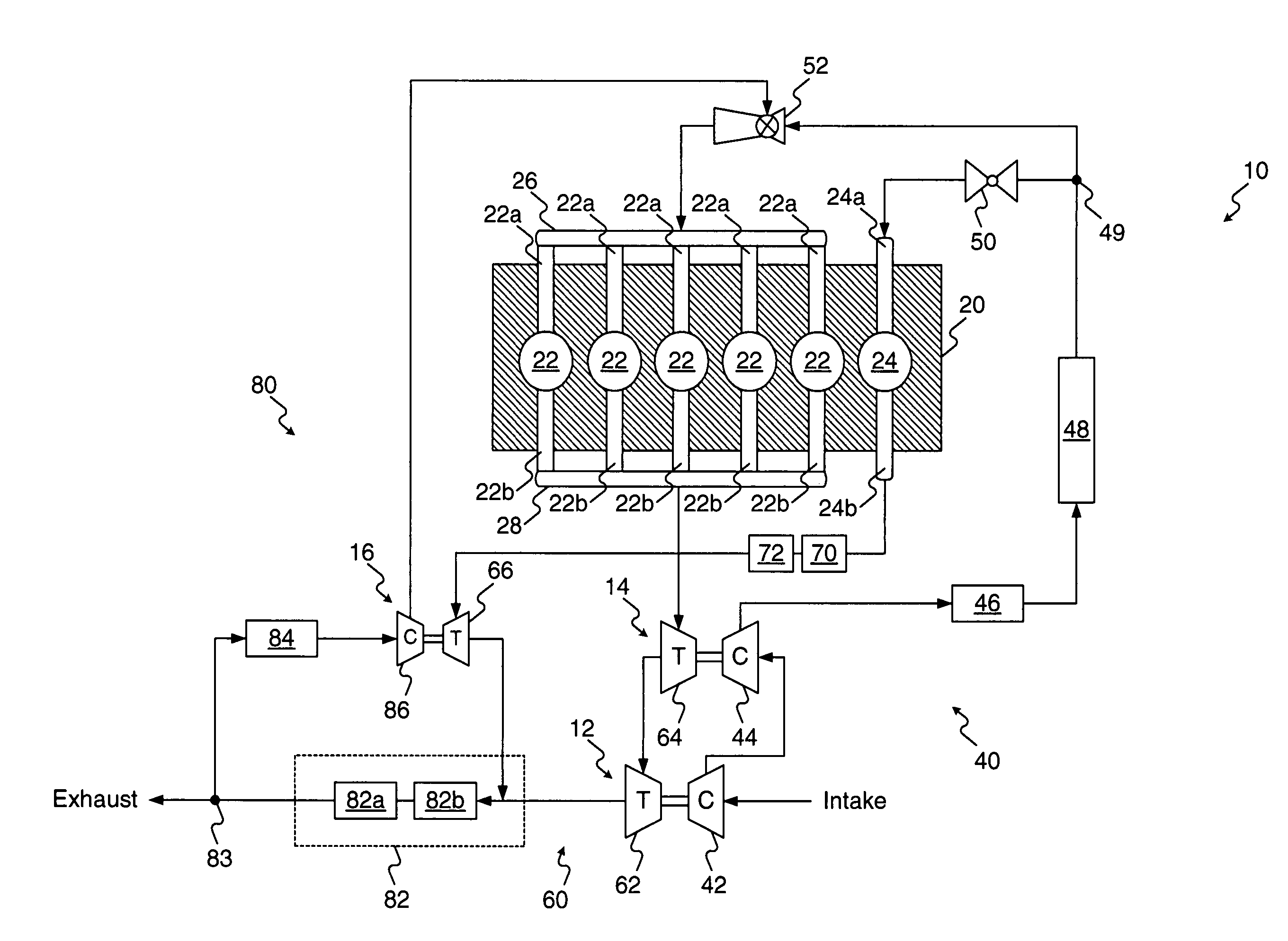
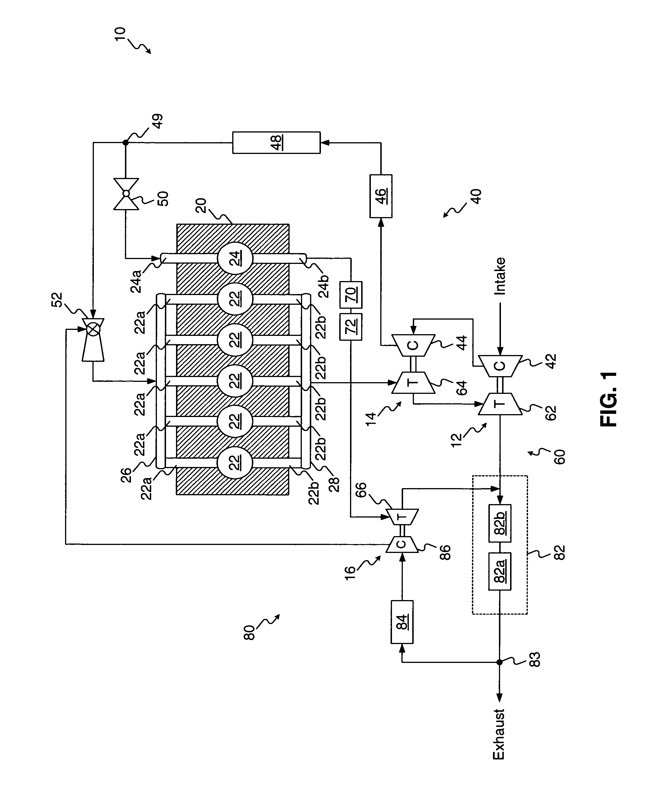
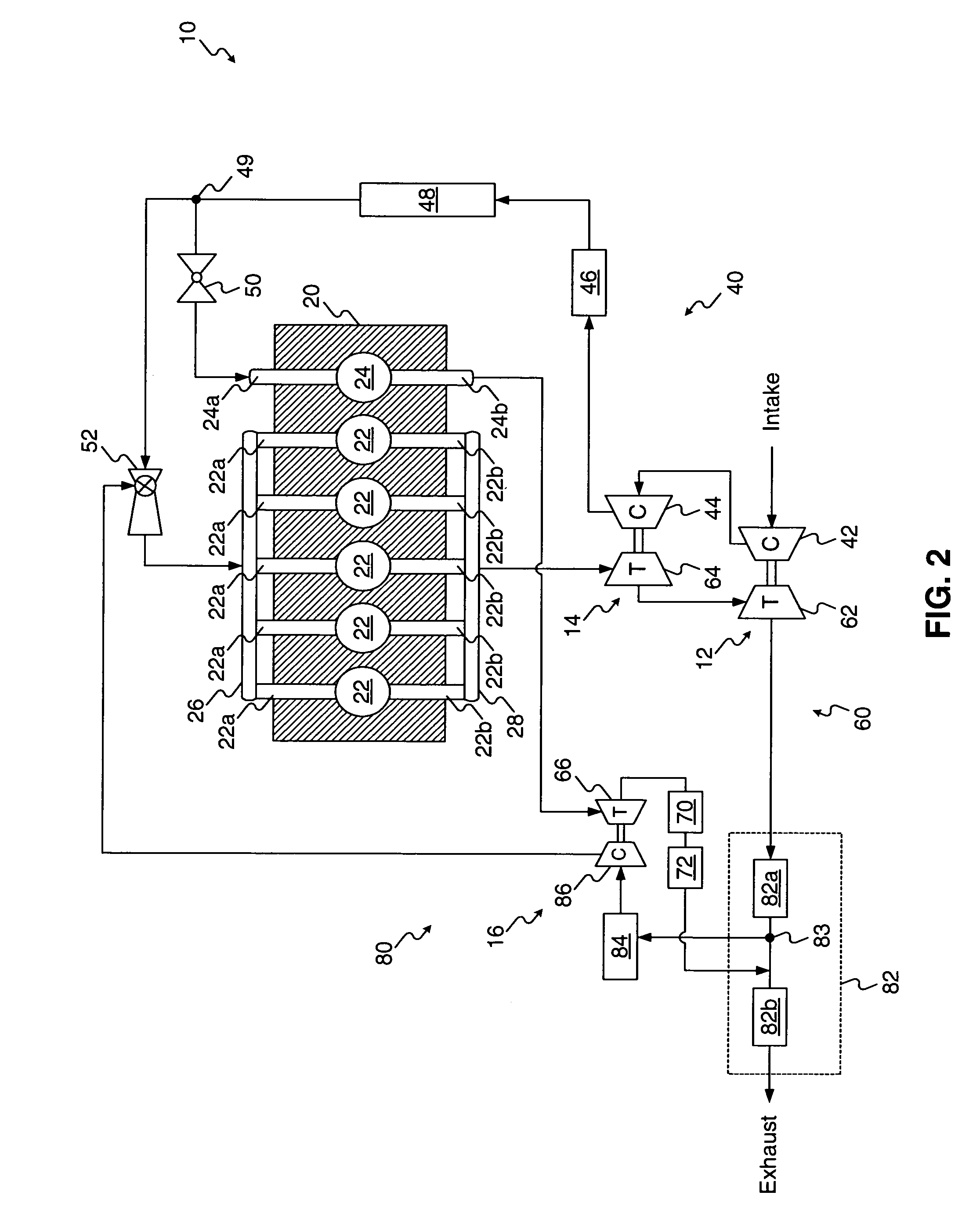
[0018]FIG. 1 illustrates an exemplary exhaust gas recirculation (“EGR”) system 10, for a powered system, such as a work machine (not shown). The exhaust recirculation system 10 includes a power source. In the exemplary exhaust recirculation system 10, the power source is an internal combustion engine 20, e.g., a diesel engine, a gasoline engine, a gaseous fuel-powered engine, and the like, or any other engine apparent to one skilled in the art. Alternatively, the engine 20 may be another source of power, such as a furnace, or another suitable source of power for a powered system, such as a factory or power plant.

[0019]The engine 20 includes a plurality of cylinders, including a first cylinder group 22 and a second cylinder group 24. Each of the cylinder groups 22, 24 includes one or more cylinders. As will be discussed in detail below, the operation of the cylinders of the cylinder groups 22, 24 depends on the ratio of air to fuel that is injected into the cylinders 22, 24 during th...


PUM


Abstract

An exhaust recirculation system includes a power source including at least one cylinder outputting exhaust gas and a particulate reducing device fluidly connected to at least one exhaust duct of the power source. The particulate reducing device is configured to reduce an amount of particulates in the exhaust gas. The exhaust recirculation system also includes a recirculation compressor configured to receive and compress at least a portion of the exhaust gas. An intake duct of the at least one cylinder of the power source is fluidly connected to the recirculation compressor to receive the compressed reduced-particulate exhaust gas.

Description

TECHNICAL FIELD[0001]The present disclosure relates generally to an exhaust gas recirculation system, and more particularly, to a turbocharged exhaust gas recirculation system for an engine.BACKGROUND[0002]Engines, including diesel engines, gasoline engines, gaseous fuel-driven engines, and other engines known in the art, may exhaust a complex mixture of air pollutants. The air pollutants may be composed of gaseous and solid material, including particulate matter, nitrogen oxides (NOx), and sulfur compounds.[0003]Due to heightened environmental concerns, exhaust emission standards have become increasingly stringent over the years. The amount of pollutants emitted from an engine may be regulated depending on the type, size, and / or class of engine.[0004]One method that has been implemented by engine manufacturers to comply with the regulation of engine emissions includes introducing a catalyst in the exhaust stream. Some catalysts are capable of removing pollutants from the exhaust ga...

Claims


Application Information

Patent Timeline
Patent Type & Authority Patents(United States)
IPC IPC(8): F02M25/06
CPCF02B29/0412F02B37/001F02B37/004F02B37/007F02B37/013F02M25/0711F02M25/0718F02M25/0739F02M25/0748F01N3/035F01N5/04F01N13/107F02B29/0425F02B29/0437F02M25/0722F02M25/073F02M25/0731Y02T10/121Y02T10/146Y02T10/144F02M26/08F02M26/15F02M26/19F02M26/27F02M26/28F02M26/34F02M26/42Y02T10/12
Inventor ROOZENBOOM, STEPHAN DONALDKIESER, ANDREW JOHN
Owner CATERPILLAR INC
Why Eureka
Try Eureka